Re: Just a thought, not an argument
Steve Voigt
Kees, me too. My planes are either old Stanleys or homemade woodies; my saws are all old Disstons, etc. Still, I can sure appreciate the quality of C&W, Sauer & Steiner, etc.
Knowledge You Can Build On — Est. 1998
Re: Just a thought, not an argument
Steve Voigt
Kees, me too. My planes are either old Stanleys or homemade woodies; my saws are all old Disstons, etc. Still, I can sure appreciate the quality of C&W, Sauer & Steiner, etc.
Some Kato/Kawai data--LONG, TEDIOUS, BORING
Wiley Horne--So. Calif.
Hello Wilbur and all,
Kato and Kawai provide data on force required to push the plane, at chipbreaker setbacks of 4 thousandths and 8 thousandths, and for chipbreaker bevels at 40, 50, and 60 degrees.
Here is a picture of the Kato/Kawai planing force data, as republished on Steve Elliott's website. Note the full reference back to Kato/Kawai paper:
http://www.flickr.com/photos/78661951@N07/10140946664/in/set-72157635012252891
At the closer chipbreaker setting (0.004"), there is a sharp jump in planing force required when the bevel angle was increased from 40 degrees to 50 and 60 degrees. This increase in horizontal force is accompanied (lower graph) by vertical force required early to hold the plane in the cut--the plane is still pulling itself into the cut at 40 degrees, but positive pressure is required to hold it in the cut at 50 and 60 degrees.
I tried to clarify these relationships by sketching a version of this graph with the variables reversed. That is, I put chipbreaker setback and chipbreaker bevel on the axes, and plotted the results (planing forces) to look for patterns. Here is my sketch, drawn from the Kato/Kawai data at planing distance, L = 100 meters:
http://www.flickr.com/photos/78661951@N07/10141190723/in/set-72157635012252891/lightbox/
The slanting lines show combinations of chipbreaker bevel and setback that require a particular level of planing force. The forces are in kilograms, 1 kg = 2.2 lb. The forces range from 2.3 kg (5 lb) to 3.3 kg (7.25 lb). The slanting lines connect combinations of bevel and setback that require that particular force to push the plane.
The main significance--allowing for plenty of error in my data interpolation and in the fact that I am pushing a mere 6 data points very hard--the main significance is the sharp slant of the lines vertically. What these lines bear out is that Wilbur's intuition is correct. In general, planing force will increase more quickly with close chip breaker than with higher bevel angle. For example, suppose we start from the middle right point--8 thousandths setback and 50 degree bevel. If we close the chipbreaker gap down to 4 thousandths from 8, the planing force required will increase 37%, from 5-1/4 lb (2.4kg) to 7-1/4 lb (3.3kg). But from that same middle right point, if we maintain the 8 thousandths setback and steepen the bevel from 50 to 60 degrees, the planing force increases by only 8%, from 2.4kg to 2.6kg (set.). Within this range of data, and subject to my estimating error, horizontal planing force required increases much faster with breaker closeness, as with higher bevel angle.
However, there are threshholds in the data. Wilbur's intuition is correct for sure at 50 degree bevels and higher. But there may be an exception if we get below a thresshold bevel angle, down around 40 degrees. At 40 degrees, when we close down from 8 thousandths to 4 thousandths, the horizontal planing force required increased by 20%, from 2.3kg to 2.8kg, compared with 37% when we started from a 50 degree bevel.
The vertical force data support the notion of a threshhold effect around 40 degrees. The numbers in parentheses are vertical force: positive numbers mean force had to be applied to hold the blade in the cut at those chipbreaker settings; minus numbers mean the plane is still pulling itself into the cut. For example, at 100 meters planed, force is needed to hold the plane in the cut at 4 thousandths setback and 50-60 degree bevels, whereas the plane is still pulling itself into the cut at a 40 degree bevel, despite the tight chipbreaker setting. So there may be a threshold around 40 degrees where the tradeoff between breaker setback and bevel is shifting in favor of maintaining a low bevel if possible. [This is assuming that the chip breaker tearout reduction is still happening at 40 degrees--Kato/Kawai do not have tearout data.]
Bottom line: It appears that in general Wilbur's intuition is right--go for the largest setback that will give good results, for reasonable bevel settings. But there may be an exception favoring low bevel, when the bevel gets low enough, around 40 degrees, which is what Kees is experimenting with. I'm looking forward to Kees' and others' experiments. For myself, I'm going to round off the chip breaker, following Warren's advice. The rounded breaker should provide the necessary bending, without unduly increasing the back-pressure on the chip, which we experience as 'getting hard to push'.
Wiley
Re: Some Kato/Kawai data--LONG, TEDIOUS, BORING
Kees
Well, you sure made something simple, very hard to understand 
Indeed it looks like the distance is more of a factor then bevel angle. Add to that the cirumstance that you can get away with a bit more distance when you use a higher bevel angle, and you would say that both would equalise each other. Theoretically.
Then there is another thing. Burnishing of the wood. I know Larry Williams thinks this is very important. Until now I haven't really detected any burnishing of the wood when planing long grain, even with very agressive capiron settings. In end grain, when the clearance angle is low enough, yes I can see it, but not yet in long grain. Still, it is something that interests me. It's even harder to investigate though, if you've never witnessed it.
Re: Subtleties of shaving deflection
wilbur
Thanks for the link. I was referring to the video in terms of the forces not being investigated, but clearly in this study they looked at the variables involved.
My take on Fig. 6 is that the force needed for a cap iron set 0.1 mm back with a 40º bevel is pretty close to a cap iron set 0.2 mm back with a 60º bevel, which supports the idea that the bevel of the cap iron and how far back it is set from the edge are somehow interrelated in terms of the force needed to push the plane.
"Well, you sure made something simple, very hard t
Wiley Horne--So. Calif.
Hi Kees,
The reason for inverting the data was to make explicit the tradeoffs between setback and bevel angle, which are embedded in Fig. 6 of the Kato/Kawai data.
Wiley
Re: "Well, you sure made something simple, very ha
Kees
It took a while before I understood your diagram and how you got the results. But I think I get it now. I agree with your theory. I wonder how it corelates with the real world. I'm going to do some more experiments. The #7 chipbreaker also fits in the #6, so I can prepare two chipbreakers, one with a steep angle, and one with a low angle. Thus I can use them side by side, see what the critical distance is for tearout reduction etc etc.
It's all very nice to theorise about a difference between a 0.1 or a 0.2 mm distance. But in real life we don't meassure the distance and set the chipbreaker wherever we think is good on that particular day.
Kato/Kawai For Dummies - my interpretation
Derek Cohen (in Perth, Australia)
Bottom line: It appears that in general Wilbur's intuition is right--go for the largest setback that will give good results, for reasonable bevel settings. But there may be an exception favoring low bevel, when the bevel gets low enough, around 40 degrees, which is what Kees is experimenting with.
Over at Sawmill Creek I joking said that "perhaps we should now refer to the angle the the leading edge of the chip breaker as the bending angle". Now I think that this has merit.
In a nutshell, what we are achieving with the combination of a close set chip breaker and the angle at its leading edge is a bending of the chip close to the edge of the blade. This we all know.
We also know that there is a relationship between the distance to the blade edge and the angle at the edge of the chip breaker. Borrowing from aerodynamics, we can understand this relationship as follows ...
Think of a sports car being tested for "slipperiness" in a wind tunnel. First we have a vintage sports car ...

What we see here are sudden uplifts of airflow when hitting the vertical sections (such as the grill and the windscreen). One would expect that this extra drag would slow down the car. Where the airflow passes over the more horizontal sections of the body (such as the hood and the roof), there is little interruption, with greater speed and/or efficiency expected.
Here is a more modern sportscar with more advanced aerodynamics ...

Another way of looking at the way the chip breaker interacts with the shaving is as an air break or wing flap on an aeroplane ...

As the air hits the flap, it is slowed down. Similarly, as the shaving hits the leading edge of the chip breaker, it is slowed down and forced upward, and forces the blade down (equal and opposite reactions).
There are three corollaries that follow:
1. the closer the chip breaker is to the edge of the blade, the greater the down force at the blade edge, and the greater the effort to push the plane.
Greater down force should also lead to increased blade wear.
2. the higher the angle at the leading edge, the greater the "braking effect" ... aka greater "bending effect".
K &K recommended an 80 degree leading edge on a 40 degree bed as optimum. It follows that the leading edge for a 45 degree bed smoother would be 75 degrees, for a 50 degree bed smoother it would be 70 degrees, and for a 55 degree smoother it would be 65 degrees.
3. a lower angle at the leading edge will reduce the bending effect, and do so progressively the further from the edge it is placed. It will also reduce the effort to push the plane.
The aim of the chip breaker effect on a bevel down plane is identical to that of a bevel up plane with a high included angle: the creation of a sudden bending effect, which is also known as a Type III chip formation ...

It is the suddenness of the bend that reduces tear out. Tear out is created when wood fibres are allowed to bend slowly and progressively, breaking ahead of the blade's edge. This is also known as a Type I chip formation ...

While some woods tolerate the slow and progressive bend, namely those with evenly formed and upward running grain, those woods with uneven and erratic grain require a plane that bends the shaving in a sudden action.
Regards from Perth
Derek
Way off
Warren in Lancaster, PA
You are way off when you equate a double iron plane with a high angle plane. A high angle plane uses a scraping action rather than cutting. But the lower the angle the cleaner the cut. Where the rubber meets the road, a double iron plane is cutting at a lower angle. And you yourself admitted just last week that higher cutting angles lead to increased wear, faster dulling.
The aim of the double iron is to have your cake and eat it too: clean low angle cutting along with control of tear out.
And then perhaps not so.
Derek Cohen (in Perth, Australia)
Hi Warren
You are focussed on the cutting action ...
You are way off when you equate a double iron plane with a high angle plane. A high angle plane uses a scraping action rather than cutting. But the lower the angle the cleaner the cut.
... while I commented on the chip formation ...
The aim of the chip breaker effect on a bevel down plane is identical to that of a bevel up plane with a high included angle: the creation of a sudden bending effect, which is also known as a Type III chip formation ...
Regards from Perth
Derek
The aim
Warren in Lancaster, PA
The aim for the double iron plane is not a type of "chip formation". The aim is surface quality.
Followup, and a new query
Wiley Horne--So. Calif.
Hi Kees and all,
Good approach with the No. 6 and No. 7. Starting with high and low bevels should quickly bring out the differences in planing ease and effectiveness (preventing tearout).
You make a good point about whether any of this applies to the real world, and 'how are you gonna measure to get specific setbacks, like 4 thousandths or 8 thousandths?'
I look at it like this. Everything Kato and Kawai did is different from everything you or I are going to do. Further, everything is happening on a scale of thousandths of an inch, not hundredths. So tiny differences in breaker or blade preparation, or blade bedding angle, the wood, the planing technique itself--all these differences and others mean that we will not replicate the KK results at their specific numerical bedding angles and setbacks.
We may get results similar to theirs, just not at those specific bevel and setback values. For example, the KK data at 100m planed, show a 'breakpoint' near 40 degrees of bevel, where the sensitivity to setback becomes much less than it was at 50 degrees bevel. Which means that if the lower bevel can be used at any reasonable setback (however arrived at) to eliminate tearout, then that will give a better planing experience than using a steeper chipbreaker bevel. The thing is, you may find that threshhold or break point 5 to 10 degrees away from where KK found it--but so what, the point is to find it.
In short, the basic principles should have real world application, even if the specific data points are impractical to achieve using our methods.
New query: One thing I am curious about is the precise mechanism of how the close chipbreaker suppresses tearout. Is it the initial bending of the shaving at the breaker edge? Or is it the back pressure on the shaving generated by bending, accordioning, Caspar Labarre folding, etc? I have a hunch that for fine shavings, it's the initial bending because the shaving doesn't have enough cross-section to transmit any back pressure to the cutting face. But for thicker shavings, it's the overall back pressure, and bending is effective due to the back pressure it creates. In this theory, the bent shaving is acting like a spring, and any back pressure on the shaving is acting to press the shaving back into place, partly offsetting the lifting force of the blade which is acting to lift the shaving and cause a 'run' along the grain ahead of the cutting face. Just a notion.....
Wiley
Re: And then perhaps not so.
David Charlesworth
Derek,
I cannot agree with that. Type 3 in Hoadley's book is the action of a sharpened cabinet scraper with no hook, (or a broken piece of glass). (I think this is miss named in the book, as most woodworking scrapers are cutting tools that work with a hook).
The Kawai / Kato film shows quite clearly that a type 2 chip formation is being created.
This is odd as the blade is only pitched at 40 degrees??
Must be something to do with the ultra close set, steep chipbreaker.
David Charlesworth
Re: Kato/Kawai For Dummies - my interpretation
Kees
Well, I don't really know what's happening down there at the edge. I don't think the shaving is really broken. I always think that the shaving is being supported, like in this picture. The capiron is pushing on the curl.
[URL=http://s290.photobucket.com/user/Kees2351/media/capiron/capironpushing.gif.html]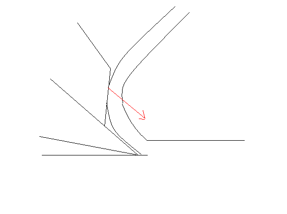 [/URL]
Anyway, I did some experiments tonight, trying to feel the difference between a steeper edge on the capiron (about 60 degrees) and a lower angle (35 degrees). First I tried to find a setting where no tearout occured. Then I took shavings in increasing thickness up till 0.1mm (12 thou) thick.
Conclusions:
- The difference in distance setting from the edge was minimal. Certainly not more then 0.1mm. Hard to meassure of course.
- To feel the difference I should have installed some force meassuring transducers in my arm. I couldn't really draw a conclusion.
So, practically speaking, the differences are minimal. I think we can safely reach a conclusion that 45 degrees is a nice angle for a capiron.
Re: Followup, and a new query
Kees
Yes, I think it will forever remain a mystery what happens EXACTLY. Regarding the thin shavings behaving differently. I guess, when the shaving has enough strength to pull itself out of the wood (tearout) it also has enough strength to support itself.
Like I wrote in another reply I didn't really feel much difference in pushing the plane with different kinds of caprion angles. It needs a more scientific approach to meassure such differences. From a practical point of view, a sharp blade is much more important. And the wooden planes are vastly lighter to push over the wood then the metal ones. The drag of the steel on wood is very obvious.
I agree with you about taking the results from Kato/Kawai too literally. For example, they had one scenario where they were making 2 thou shavings against the grain and no caprion, without any tearout. Most other scenarios were at 4 thou. Well, we all know that 2 thou certainly is no guarantee against tearout!
Re: And then perhaps not so.
Derek Cohen (in Perth, Australia) This is odd as the blade is only pitched at 40 degrees?? Must be something to do with the ultra close set, steep chipbreaker.
The Kawai / Kato film shows quite clearly that a type 2 chip formation is being created.
Ahha David, I see where we are talking at cross purposes .... and in agreement (if that makes sense).
I went hunting on the Web for a picture of the correct chip formation, then used the notation on the page, which was incorrect. The information there refers to a Type 3 chip as being the same as your Type 2 chip.
Link: http://en.wikipedia.org/wiki/Chip_formation
We are on the same page if we are agreeing with this chip formation (from Steve's website) ...
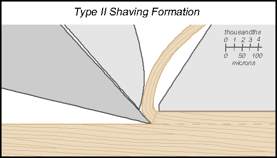
Now the point is, when you note, "Must be something to do with the ultra close set, steep chipbreaker", that is what I was trying to explain with my post. (Also why greater force is required to push the plane when the chip breaker is moved to the edge of the blade).
If I am way out, then at least I had fun putting it together.  However, I do see this as a reasonable explanation of how the chip breaker affects the formation of the chip, per se. The relevance of this is that we begin to understand why and not just accept what.
Regards from Perth
Derek
Shavings
Warren in Lancaster, PA
I am glad to see that somebody realizes that we use the word shaving for a plane's effluent. I have no idea what delineates various types of shavings, but the diagram you show seems like a bit of fantasy. There is a nice scale on the diagram; using the scale I measured the following.
Bed angle 49 degrees
Mouth (horizontal) .0008 inches
Cap iron .0022 inches
Cap iron angle 60 degrees
Shaving thickness .0015 inches
These figures are not in the range of what I have used for forty years. If somebody actually uses this configuration, I can see why the plane pushes hard. I think that if the effort to push a double iron plane approaches the effort needed to push a 55 degree plane, you have managed to miss the sweet spot.
Very humorous Warren
Derek Cohen (in Perth, Australia) Bed angle 49 degrees These figures are not in the range of what I have used for forty years. If somebody actually uses this configuration, I can see why the plane pushes hard. I think that if the effort to push a double iron plane approaches the effort needed to push a 55 degree plane, you have managed to miss the sweet spot.
I am glad to see that somebody realizes that we use the word shaving for a plane's effluent. I have no idea what delineates various types of shavings, but the diagram you show seems like a bit of fantasy. There is a nice scale on the diagram; using the scale I measured the following.
Mouth (horizontal) .0008 inches
Cap iron .0022 inches
Cap iron angle 60 degrees
Shaving thickness .0015 inches
Did you really measure Bruce Hoadley's illustration in Steve's article?
Regards from Perth
Derek
Re: Very humorous Warren
Kees
Humourous or not, but I find it very difficult to set the capiron at 4 thou (0.1mm). Let alone at 2 thou, that seems impossible for mere mortals!
Setting at 8 thou is no problem, and luckily that's usually close enough.
A bit of a fantasy
Steve Elliott
The diagram in question is my work and I'll be the first to admit it is a bit of a fantasy. It was done to illustrate Type II shaving formation, not to give instruction on setting a chipbreaker. If I recall correctly (after eight years) the bed angle is based on Norris planes. The chipbreaker distance was chosen before I had heard of Kato and Kawai and before I had measured my own settings, so there's the fantasy part. The tiny mouth was drawn to show that in theory it is possible to use a small mouth without causing the shaving to clog.
The shavings I get from smoothing planes all seem to be Type II, meaning that they aren't a series of broken segments. To get a Type I (segmented) shaving I have found it necessary to increase the shaving thickness to much more than a few thousandths.
I hope further discussion will focus on what happens during shaving formation rather than on the deficiencies of my diagram.
Offsets are everywhere
Bruce McCrory
Our standard copy machine paper (20-lb) is about .0045" thick. Some notepad sheets are .003. You can feel the difference. Rip the double blades from a disposable razor--Gillette is easy--and you have about .003-inch thickness; and a clean edge for registration. I think DE razor blades are close to .007 - .008", but they are troublesome to use as feelers for CB offset, having only the sides available.
High pitch compared to chipbreaker
Kees
I have been thinking a bit about this. So, without doing actually any testing, just from memory and hearsay, I think that a high pitch plane behaves completely different from a close set chipbreaker. There are just too many differences in how they perform. I can't do any microscopic investigation to the beahviour of the shaving near the edge, but here are my points:
- The shaving looks different. In a high pitch, single iron bevel down plane the shaving looks like an accordeon. In a plane with a properly set chipbreaker the shaving looks quite straight, maybe with a bit of waves in its surface.
- Pushing the high pitch planes is harder to do.
- The edge wears faster in a high pitched plane.
- The wood surface looks different in moderately hard hardwoods.
So I guess the shaving formation is different too and you can't really compare them.
Like I said, this is just armchair theorising. I welcome any corrections.

Re: High pitch compared to chipbreaker
craigd
high pitch plane behaves completely different from a close set chipbreaker
In my experience that is a reasonable conclusion. But, as usual, it depends.
The shaving looks different. In a high pitch, single iron bevel down plane the shaving looks like an accordeon.
Usually true. BD/BU, I don't think it matters, it is the cutting angle that matters.
But, but, but:

Three planes, BD same geometry (50°-55°), three different levels of fiber breakage. However, you wouldn't confuse any of them with the completely unbroken straight shaving from a properly set CB 45° plane (which is really for me to achieve).
The wood surface looks different in moderately hard hardwoods.
This may very well be true but I don't have any lowish angle planes that are good enough to show it. I got a decent surface on this maple or cherry (I forget which) at 55°:
Re: High pitch compared to chipbreaker
Kees
>>The wood surface looks different in moderately hard hardwoods.
>This may very well be true but I don't have any lowish angle planes that are >good enough to show it. I got a decent surface on this maple or cherry (I >forget which) at 55 °:
For me this is mostly hearsay too. I think I am not critical enough to see much difference.
Re: High pitch compared to chipbreaker
craigd
Actually, I do believe that a lower angle, more slicing cut can achieve a "cleaner" surface (those super surfacers achieve amazing results) vs a higher angle more scraping cut (my mental models tend to be chisels and draw knives). But wood is so hugely variable, I don't have the skills to make a Bailey shine (without rebuilding it) and am too cheap to buy a decent Japanese plane. But the idea of a low angle (~40°) BD infill w/CB is pretty tempting even if the clearance angle is on the low side.
Re: High pitch compared to chipbreaker
Kees
You just gave me an idea! I want to makes a couple of planes this winter and I am now collecting ideas like this. Making run-of-the-mill 45 degree coffin planes makes no sence, because I can buy these easilly.


