WoodCentral Forums

Est. 1998 — 27 years of woodworking knowledge

Dining room carver chairs - Take 2

Table of content

Table of content

Posts

Dining room carver chairs - Take 2

Edited #1

Related:


Part 1 - Introduction

About a month ago I began a thread about designing and building two carver chairs to accompany the 6 bentwood chairs we have owned for the past 40 years. The chairs were purchased all those years ago along with a table, which is around 200 years old. We need a larger table, and time has come to replace it and add two more chairs.
8.jpg
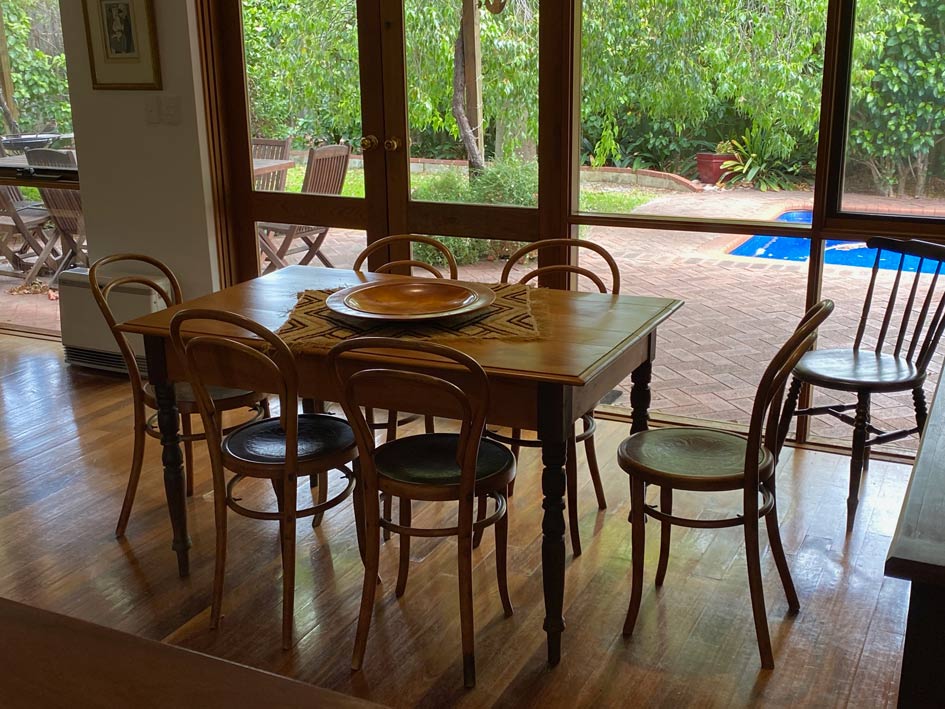
The table planned will be a modern version of this, in Hard Maple and round Jarrah legs. The carver chairs need to match the table and blend with these chairs. Our taste is minimalist, Mid Century Danish, modern. An example of the lines I seek is this sofa table I built several years ago ...
28a.jpg
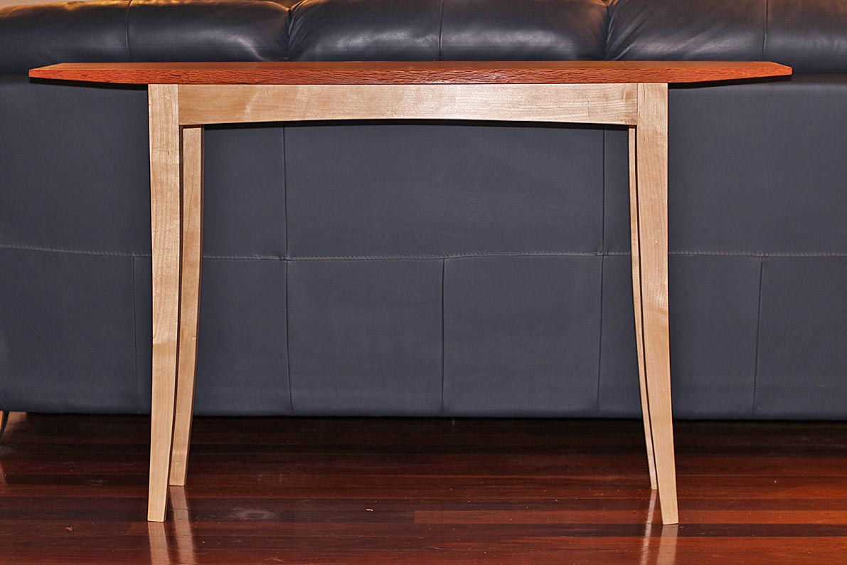
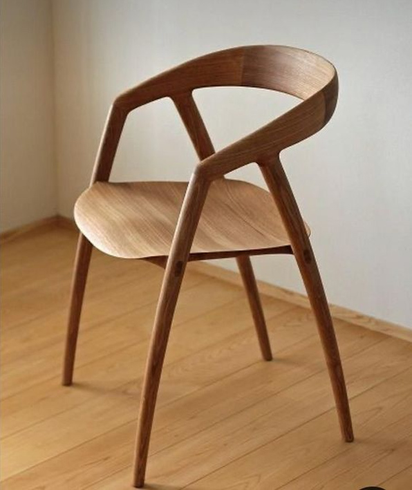
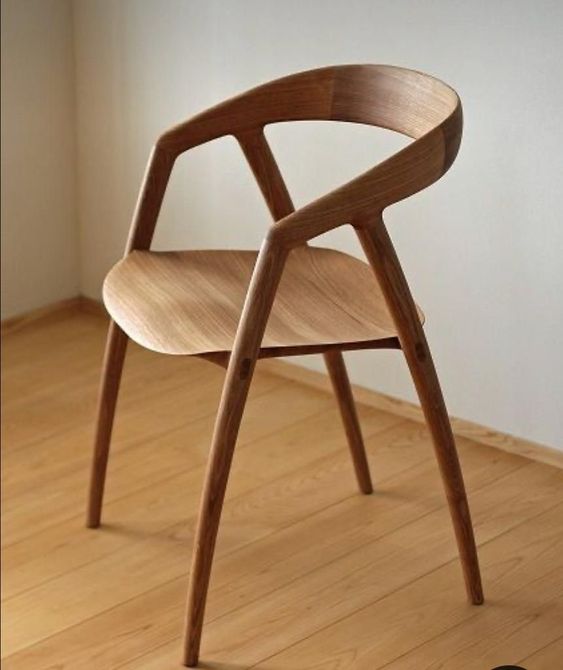
So I started thinking about the chairs I would build, and I took inspiration from this picture ...
est-living-sorrento-light-house-wolveridge-architects-3-750x540.jpg
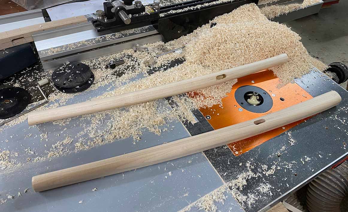
... and began to evolve a design along similar lines. The 8 legs were started (just need rounding) and the seats carved, and then the tenons were cut. And that is where the problem arose. I had this idea for integrated tenons into through mortices in the legs. Very few chairs are built like this, and for a good reason - you cannot control for run out in the tenons, and run out make for weak tenons. And that is what I discovered. So I stopped the build, and decided to begin again from scratch.
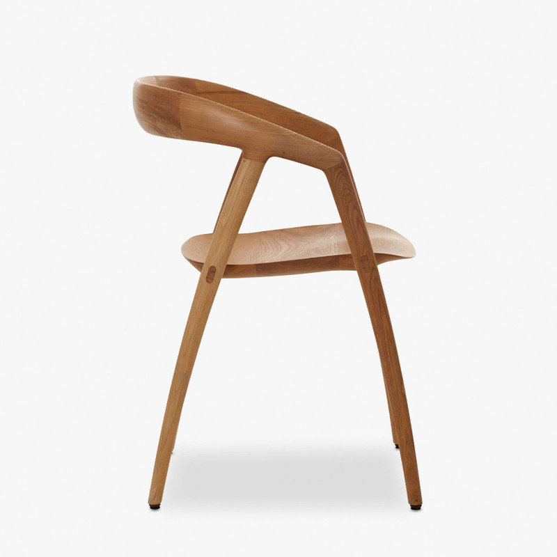
I started looking more carefully at the chair I had come across and had treated rather casually. It has a name: DC 09, and it was designed by the Japanese- Scandinavian duo, Kyoko Inoda and Nils Sveje, in 2011. It is built by the Miyazaki factory in Japan.
Chair-seat9.webp
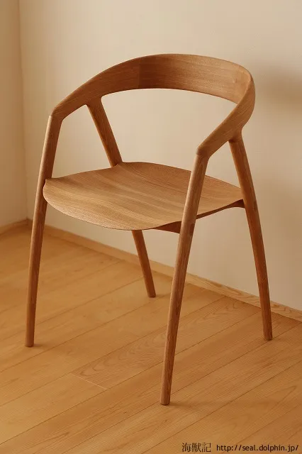
There is a challenge here - can I replicate it purely from photos? This is unlikely since one needs to examine an object in three dimensions to discover the subtleties of the design and construction. I have experience of this, having made an exact copy of Hans Wegner's "The Chair" or the "Round Chair" several years ago. What made this possible is that I own an original. One is mine and one is Wegner's ...
The-Chair.jpg
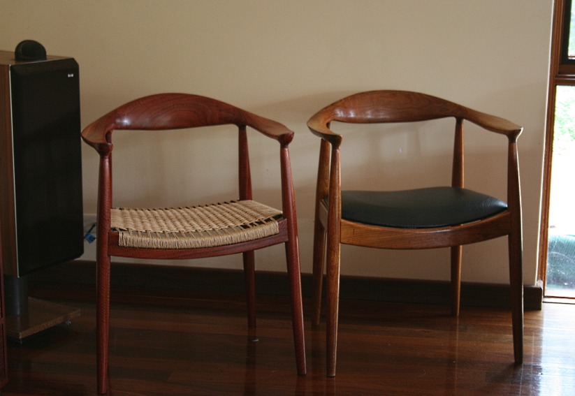
So the chairs I build will not be exact, but hopefully close. Actually, I am still on the fence about the arms and back and may modify this ... but will will see. We need to start with the seat. That is the key.
Help comes from two video I found ...
https://www.youtube.com/watch?v=5yLS-aoBXNI&ab_channel=yasuhiromurai
https://vimeo.com/438408781
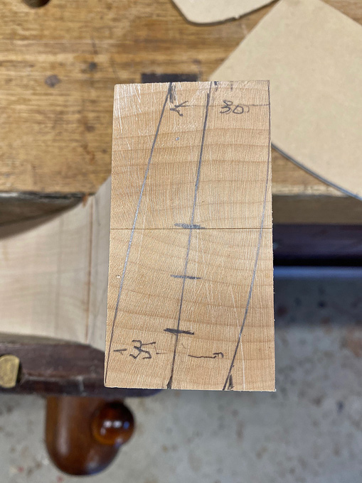
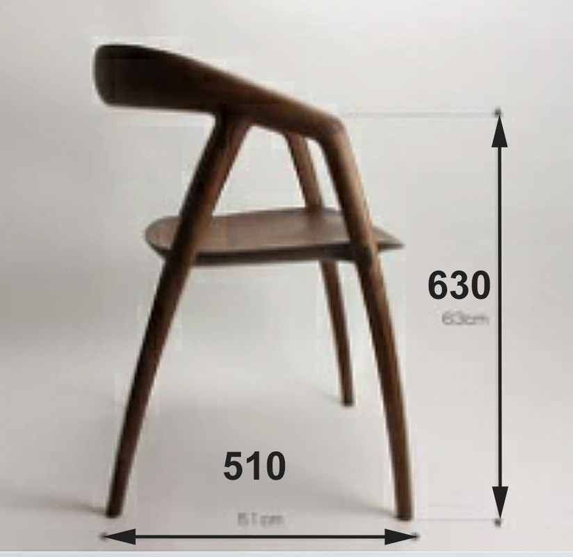
Some dimensions:
Chair-plan1.jpg
Chair-plan2.jpg
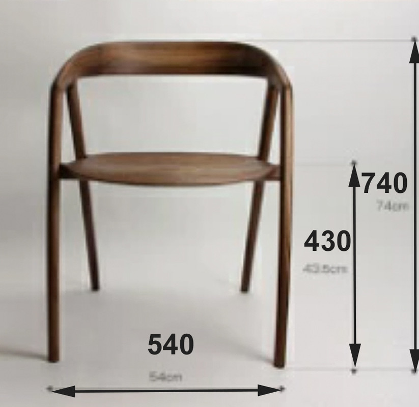
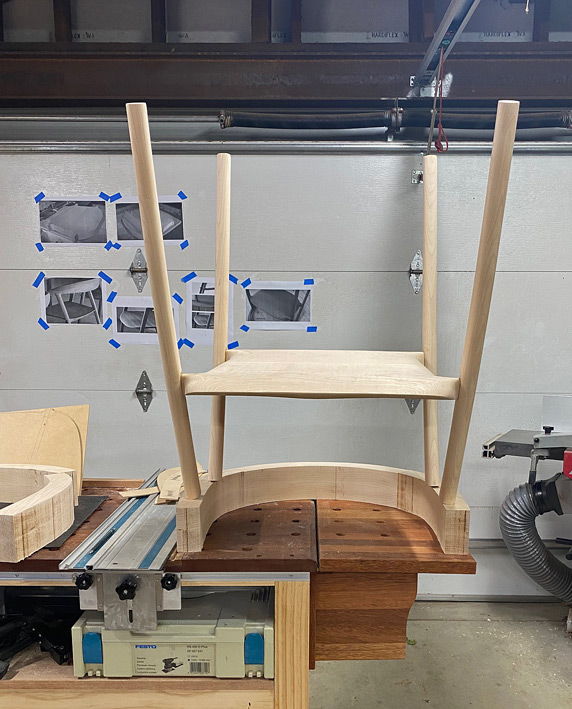
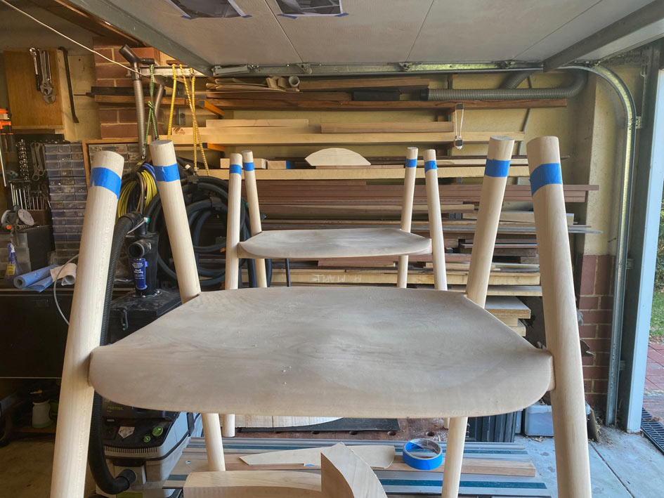
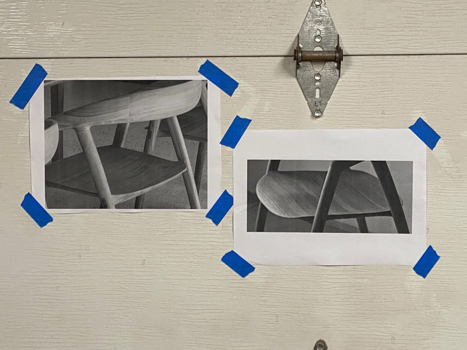
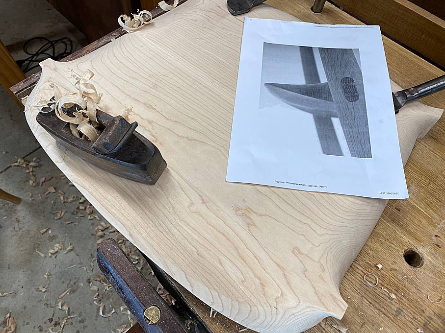
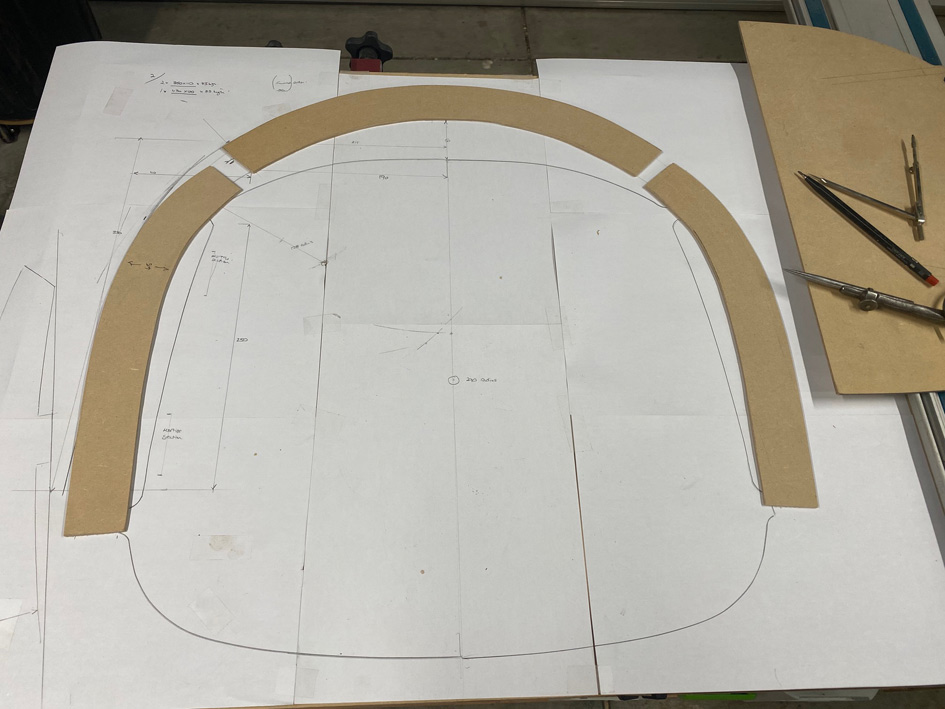
The doors above my bench make a place to pin details and photos ..
New1.jpg
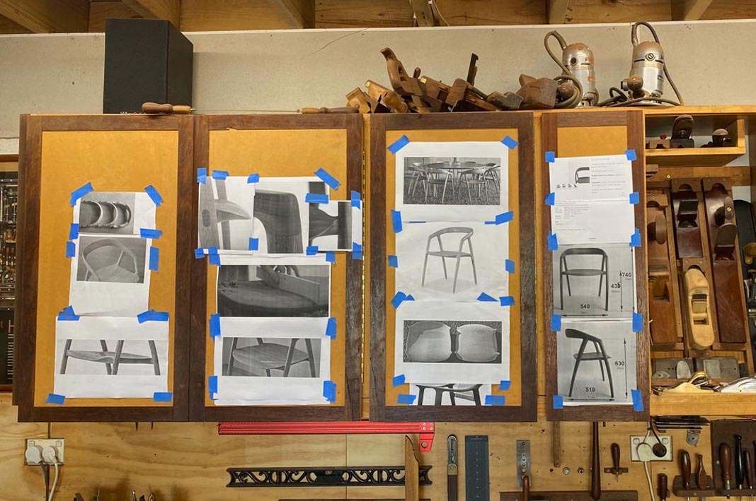
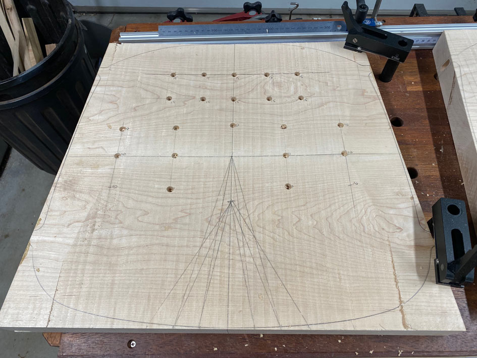
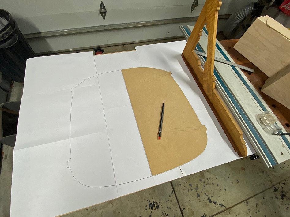
The seat plan was scaled and drawn using images from the videos and photos.
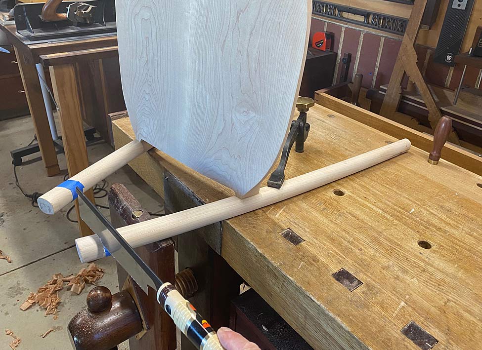
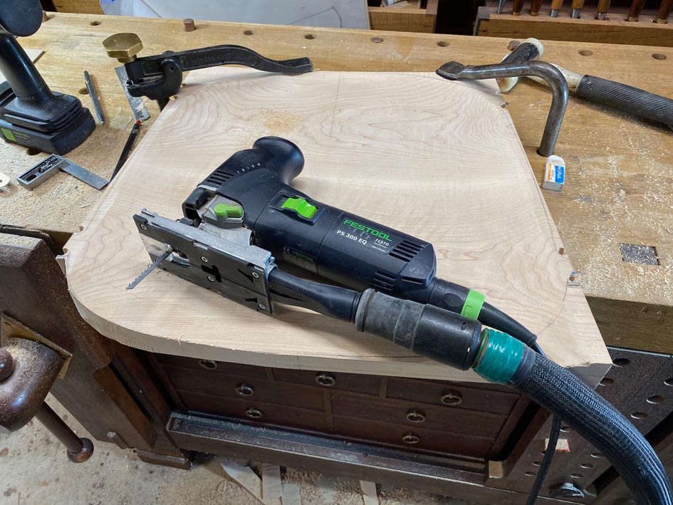
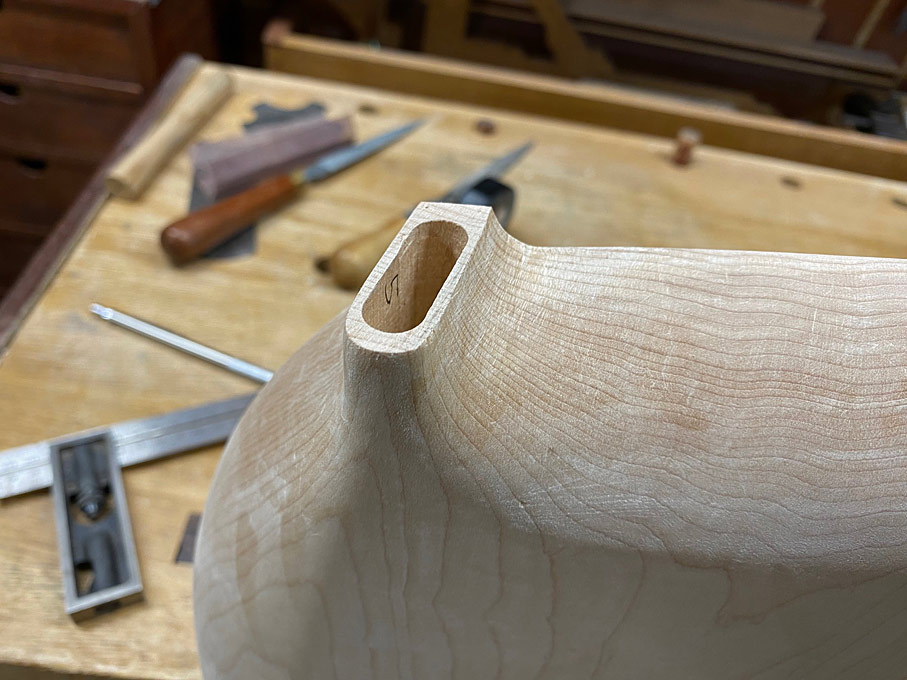
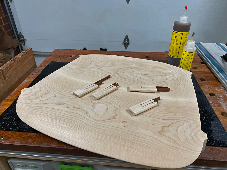
Two half-templates were created - the first was a straight-sided outline of the seat. The reason for this is that I planned to use loose tenon joinery, which would enable the tenons to have straight grain for maximum strength, and the mortices would be made using a Domino. These would be 30mm long x 10mm wide, in other words would use custom-made loose tenons. The straight sides would make it easier to cut the mortices ahead of shaping the seats.
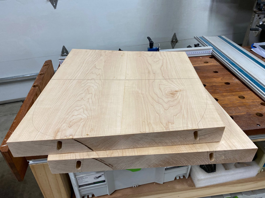
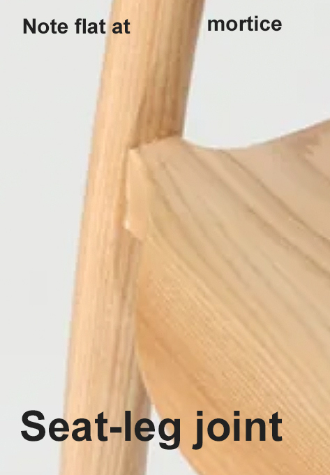
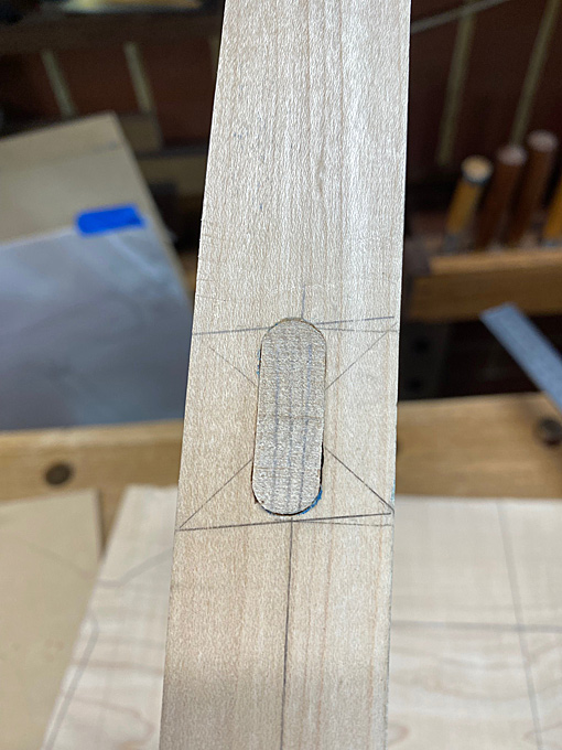
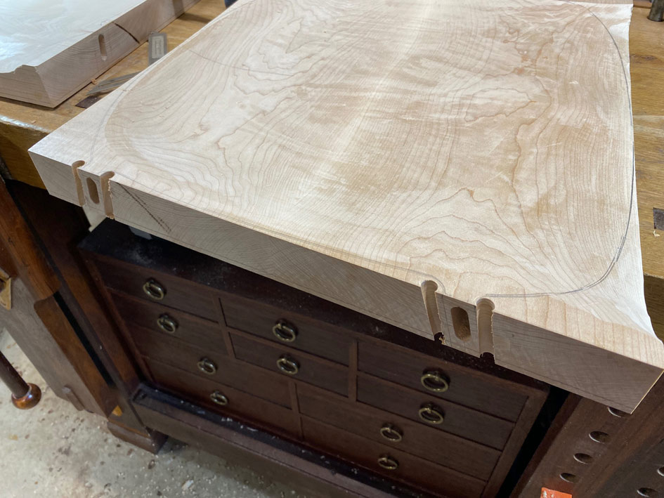
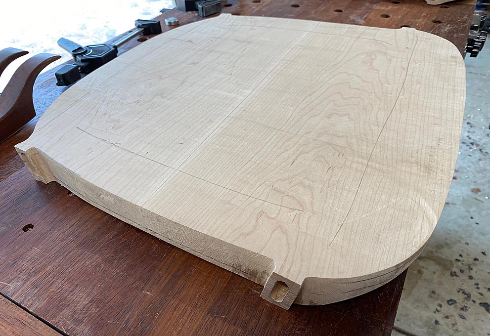
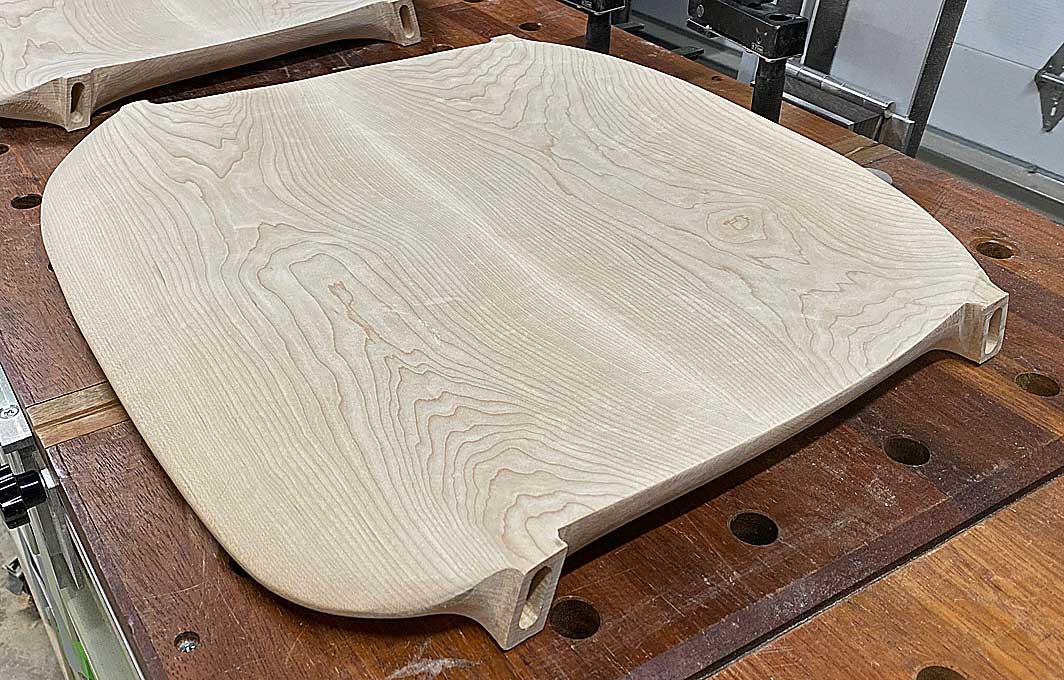
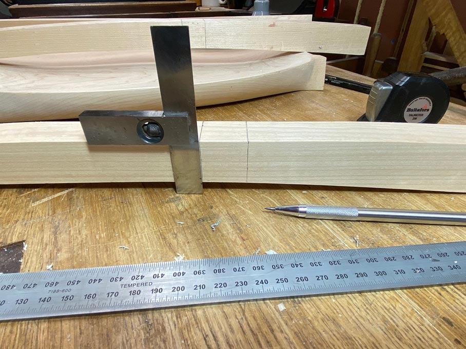
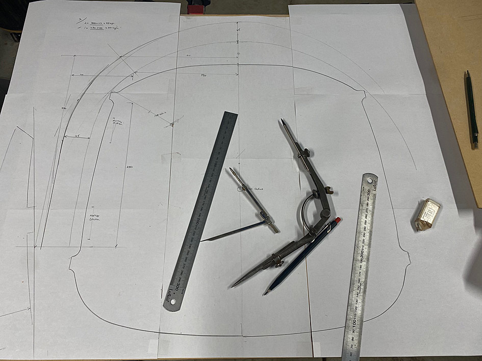
The second half-template was the actual outline of the seat, and this positions the tenons.
New3.jpg
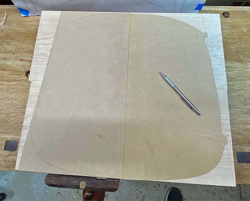
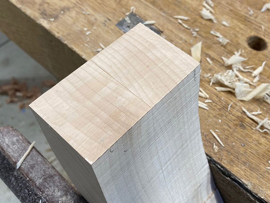
Here the tenons are positioned ...
New5.jpg
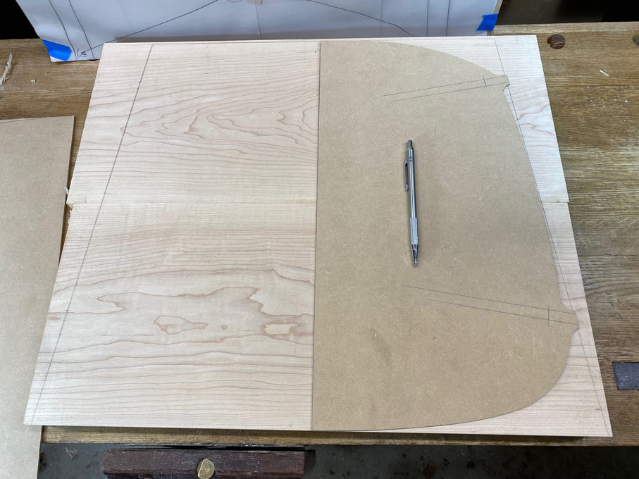
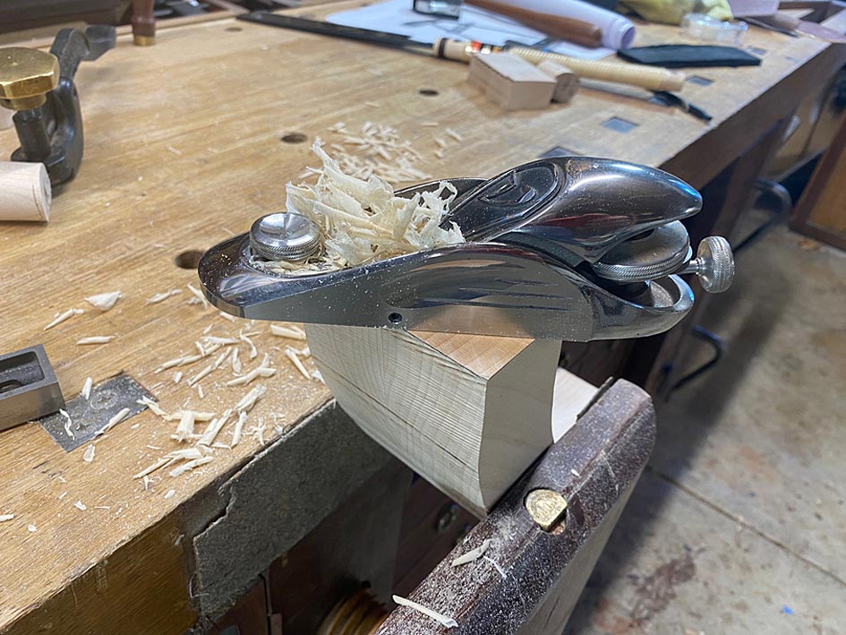
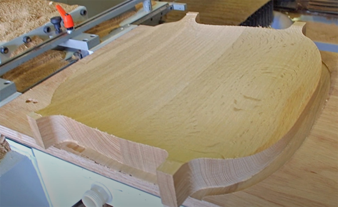
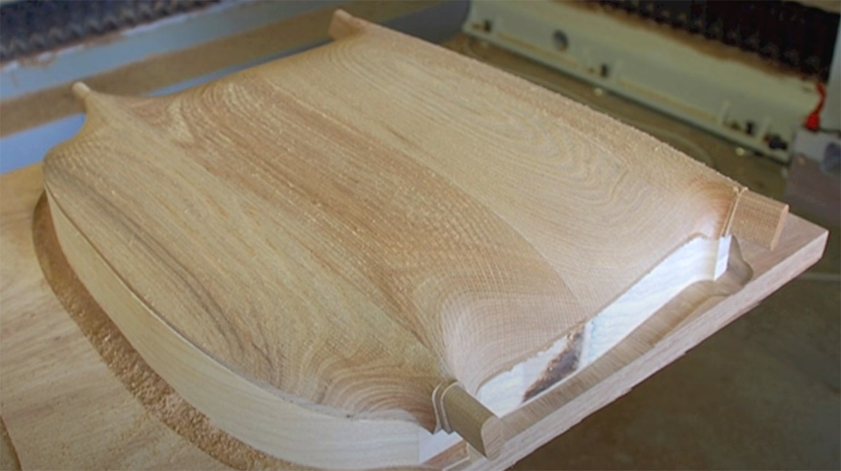
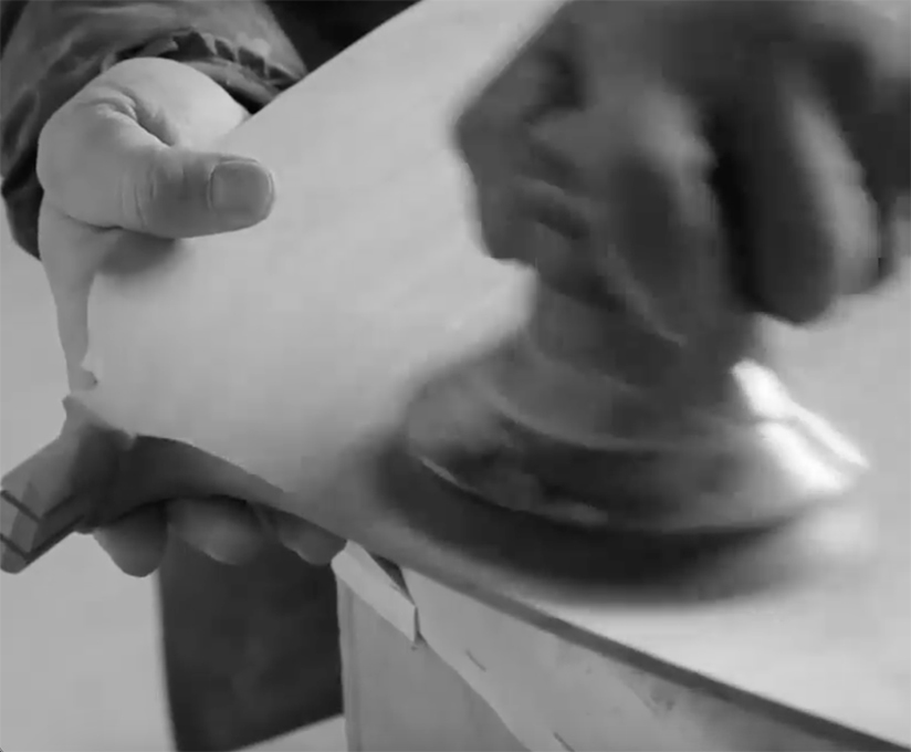
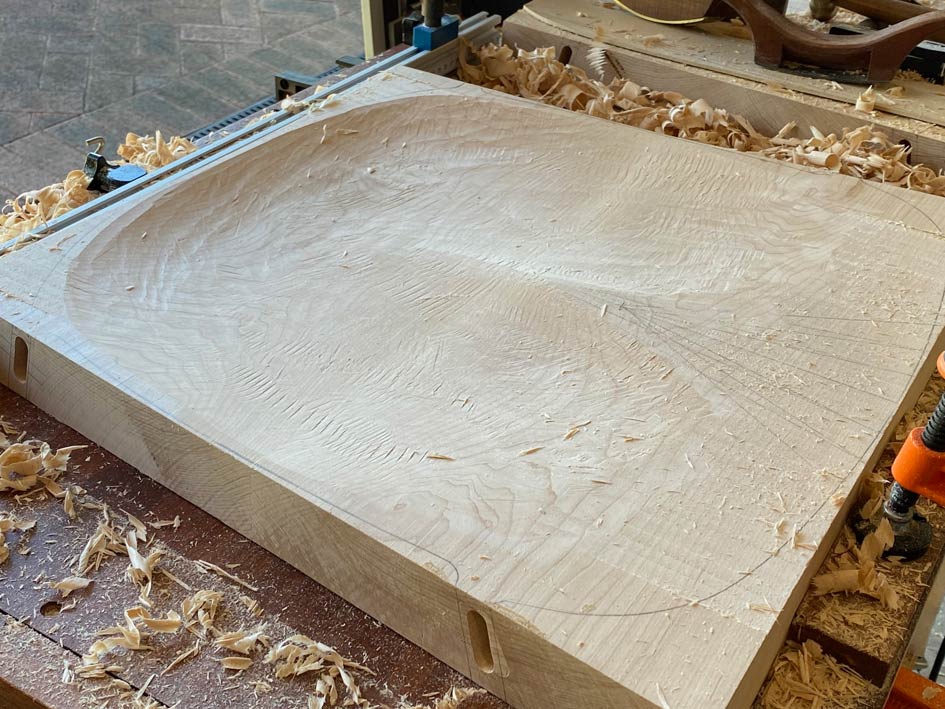
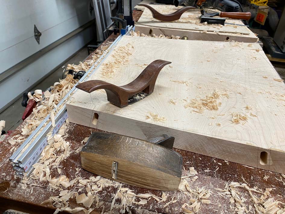
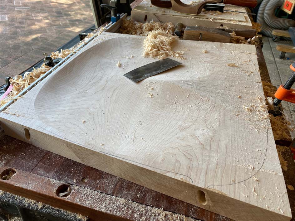
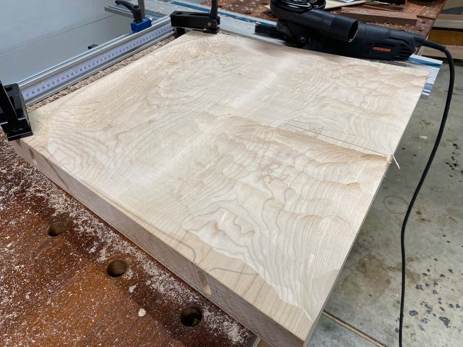
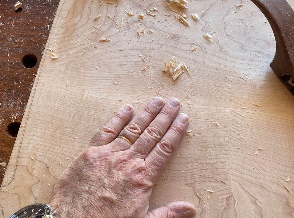
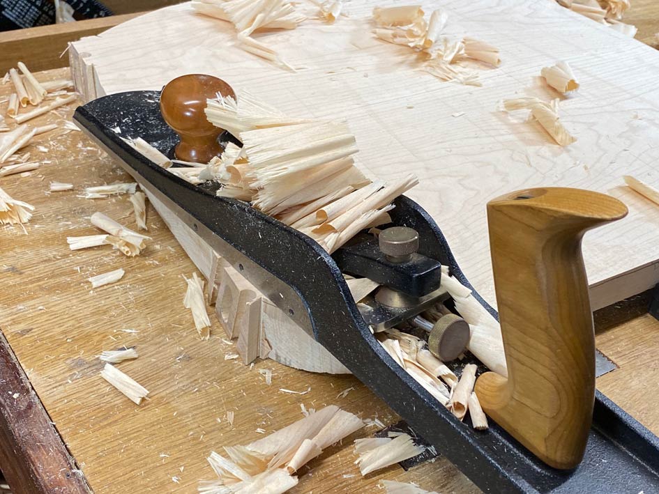
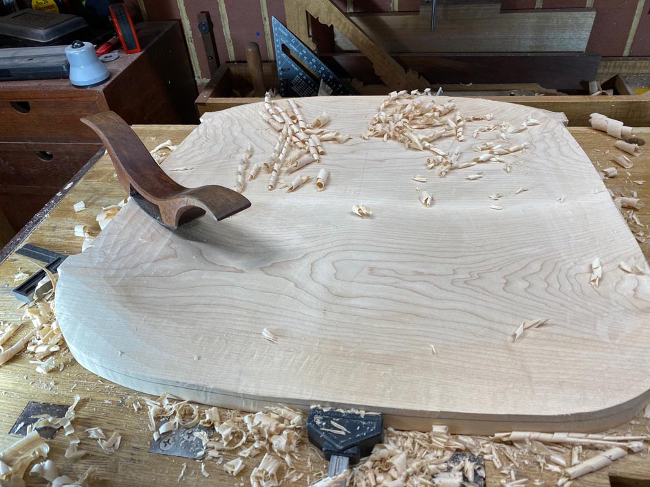
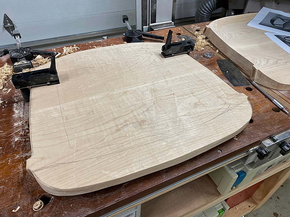
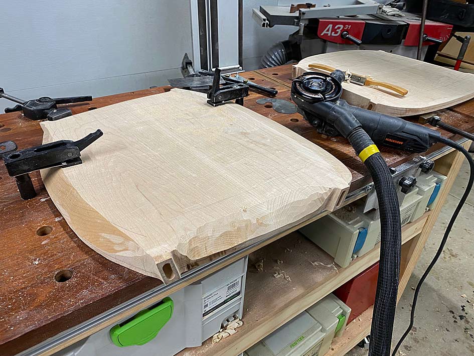
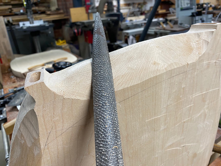
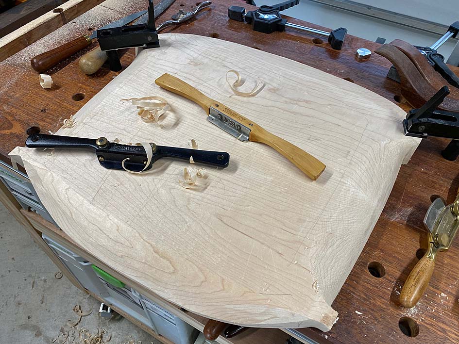
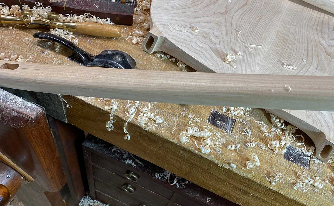
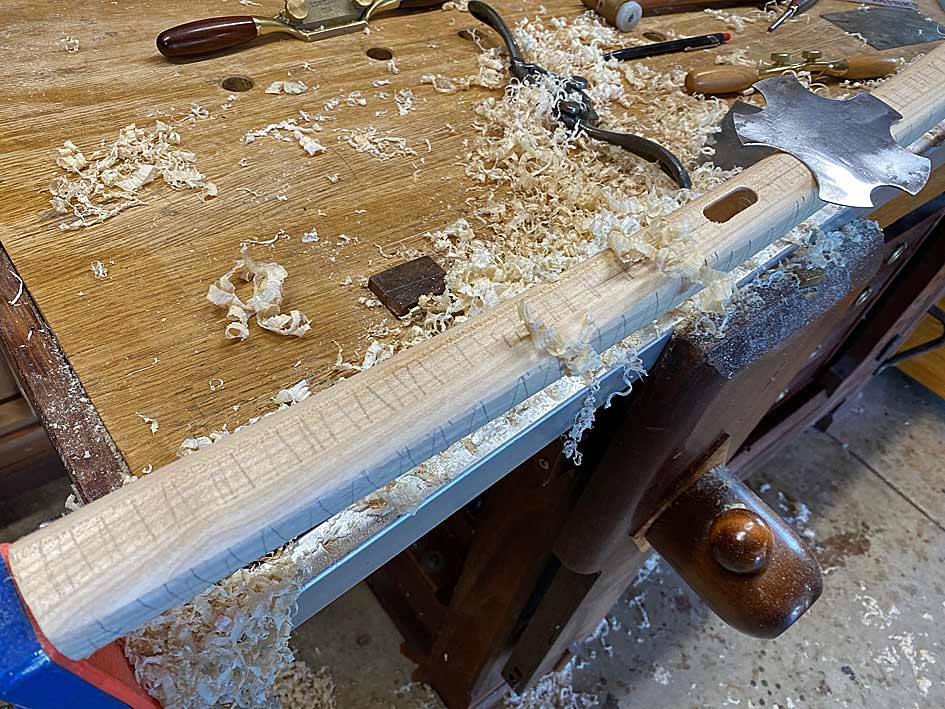
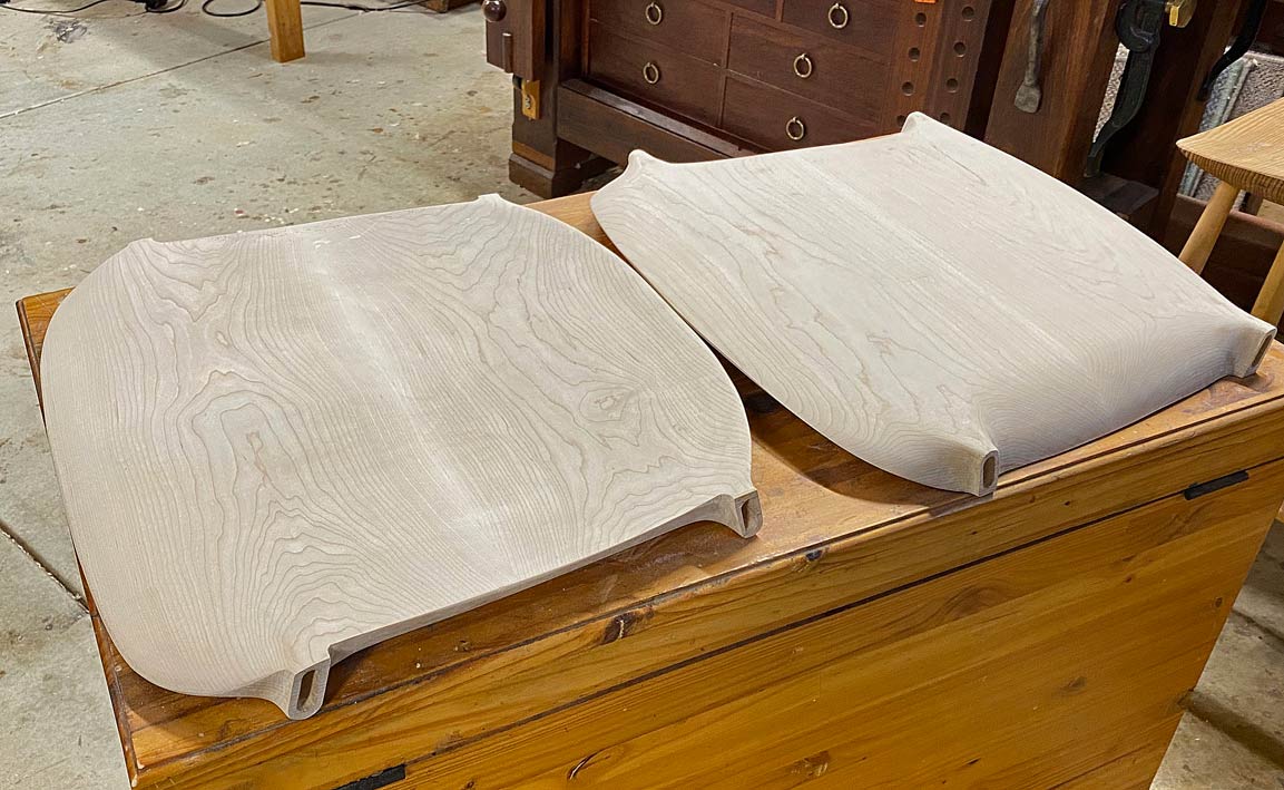
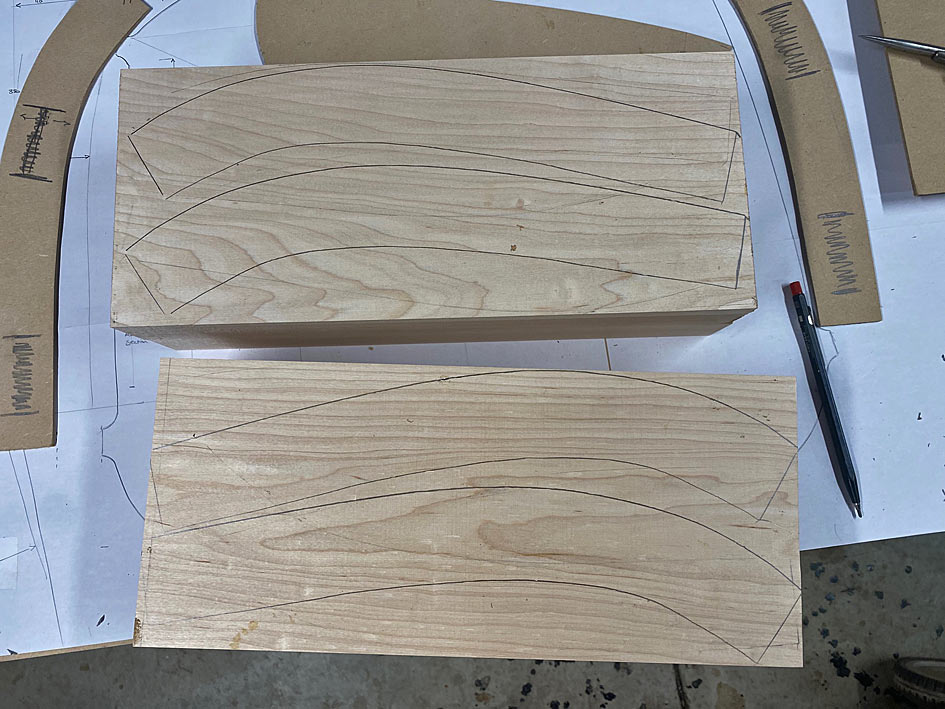
A little jack-planning to flatten the underside of the seat blanks ..
New6.jpg
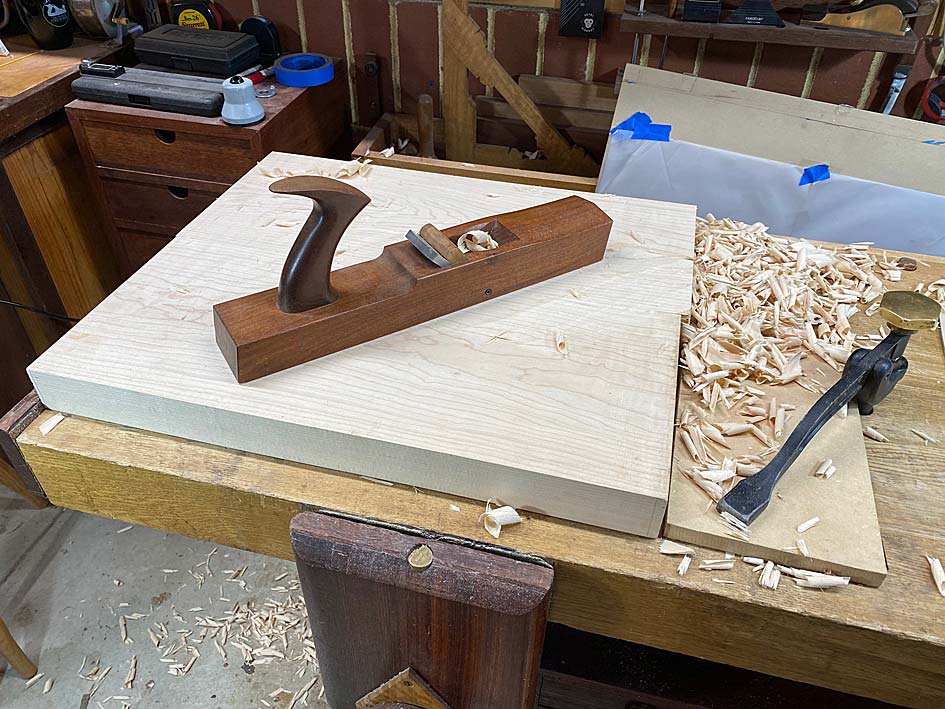
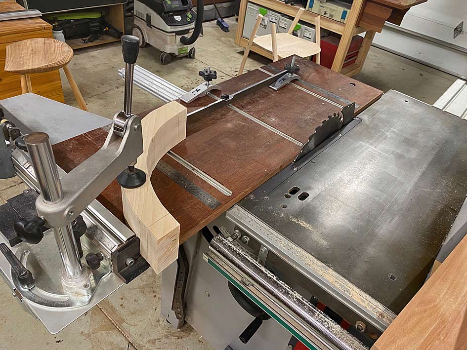
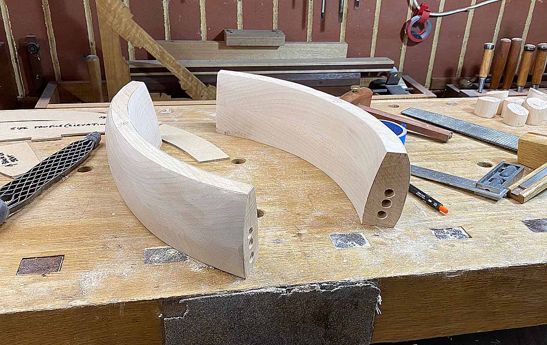
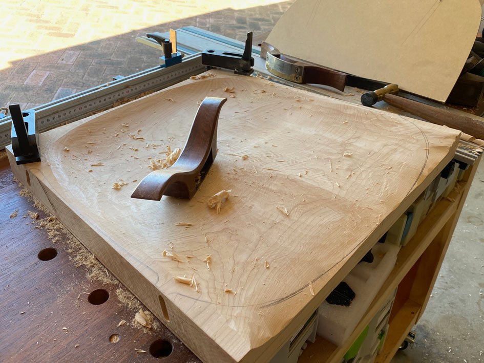
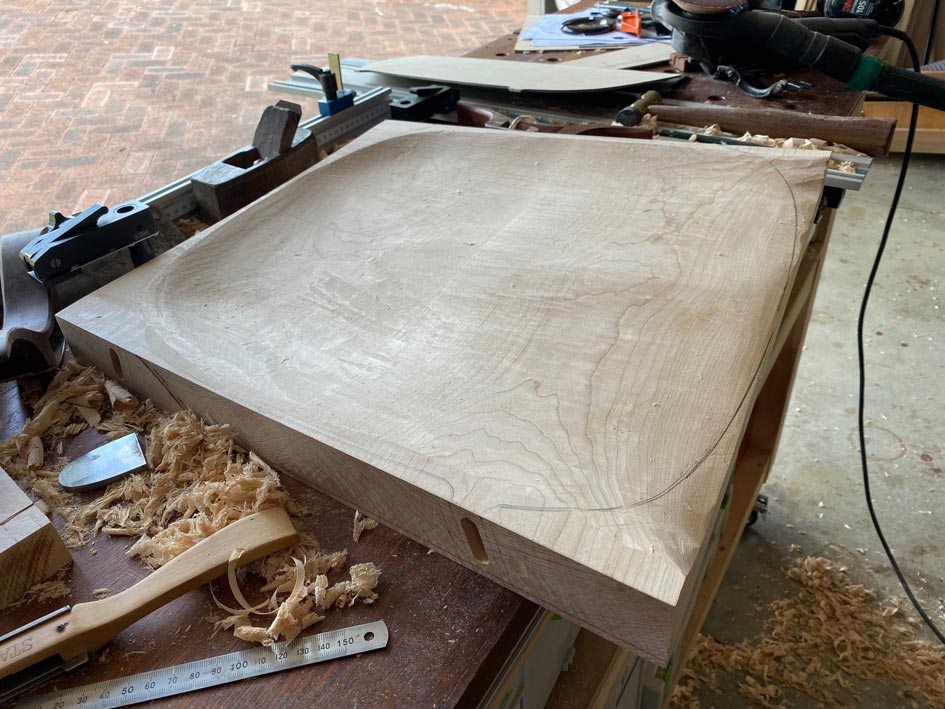
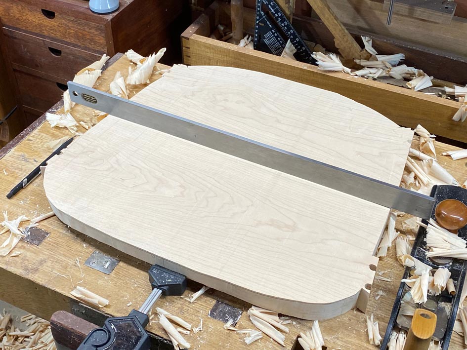
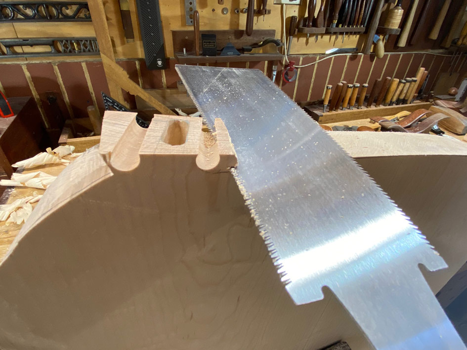
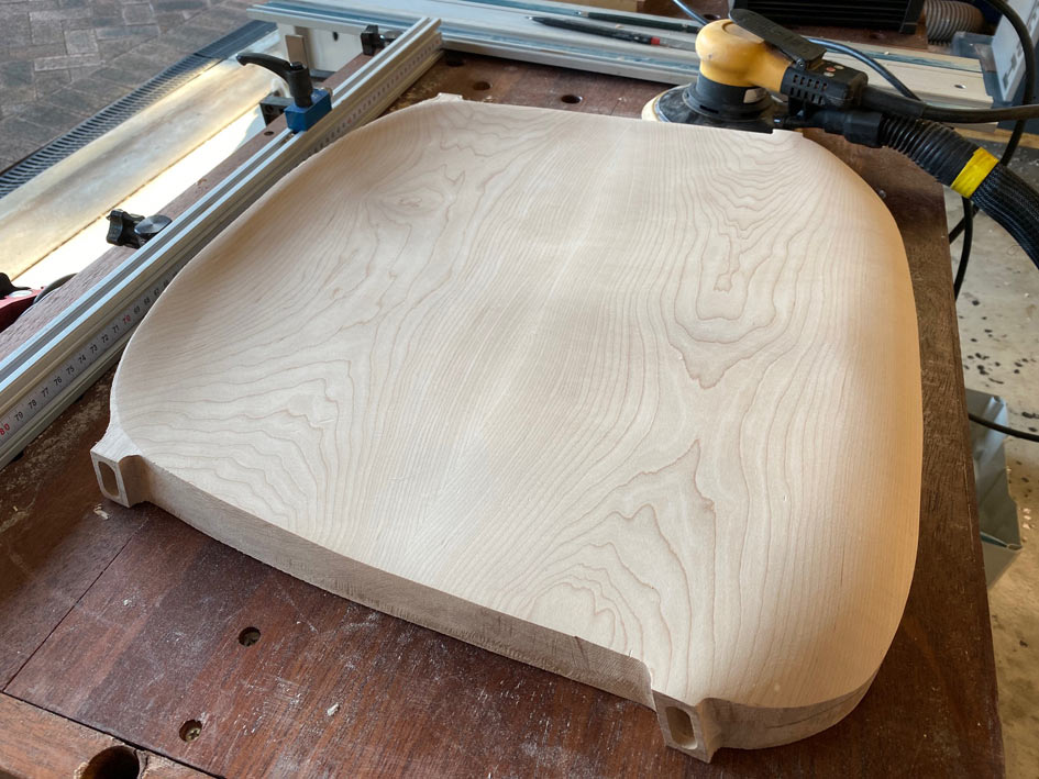
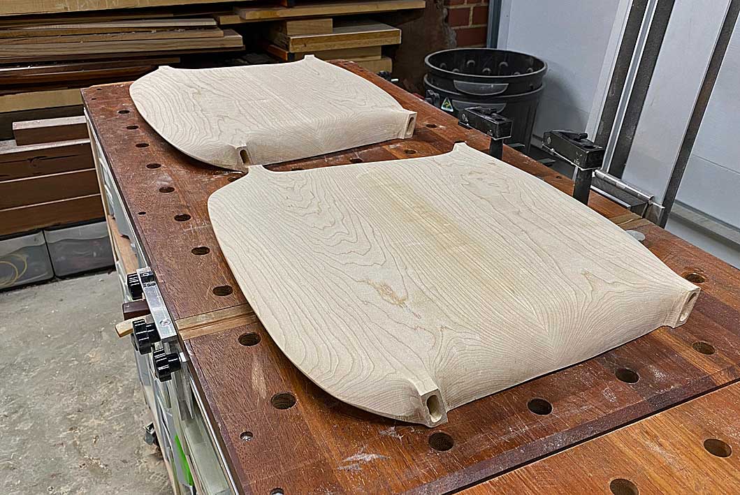
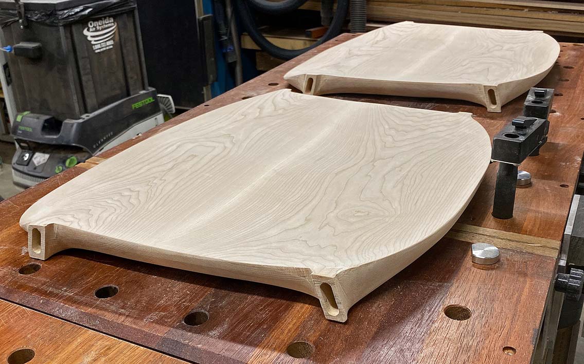
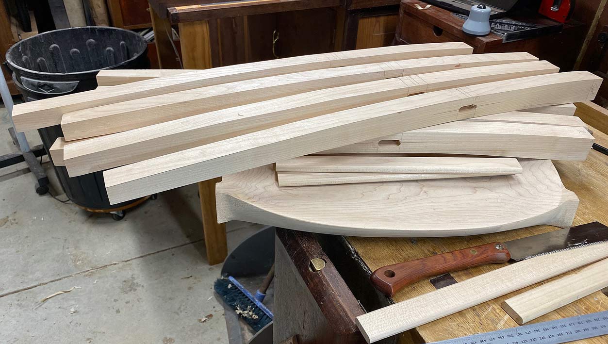
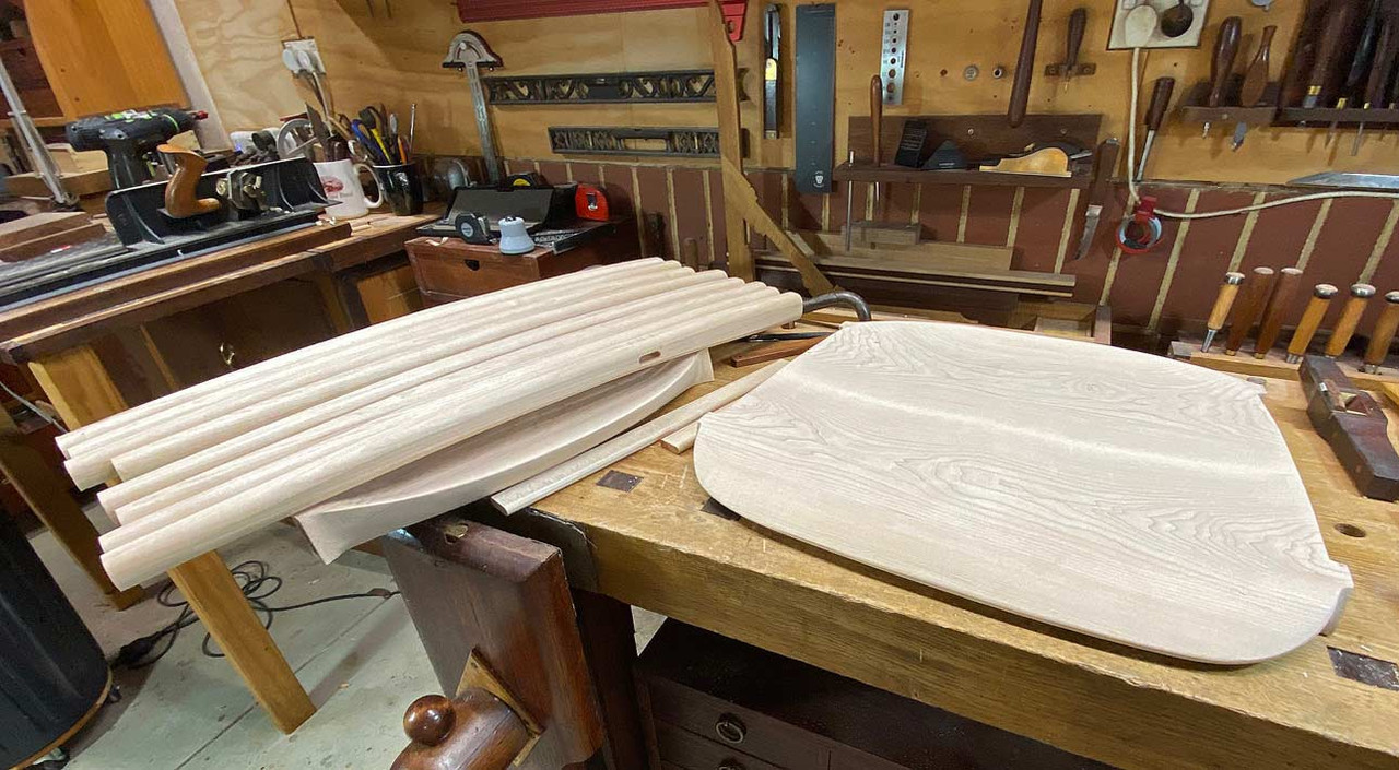
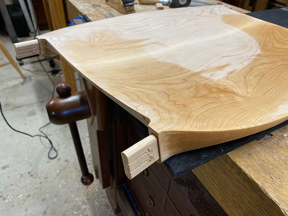
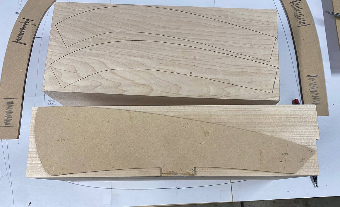
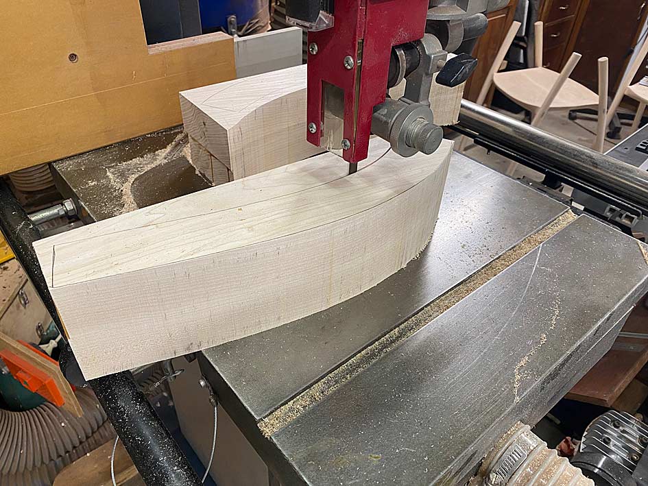
These are now sawn to shape ...
New7.jpg
New8.jpg
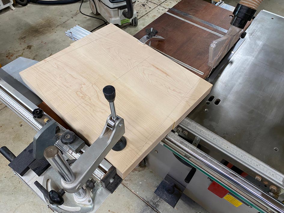
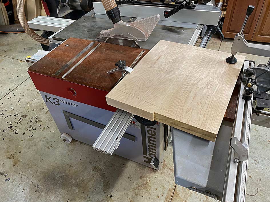
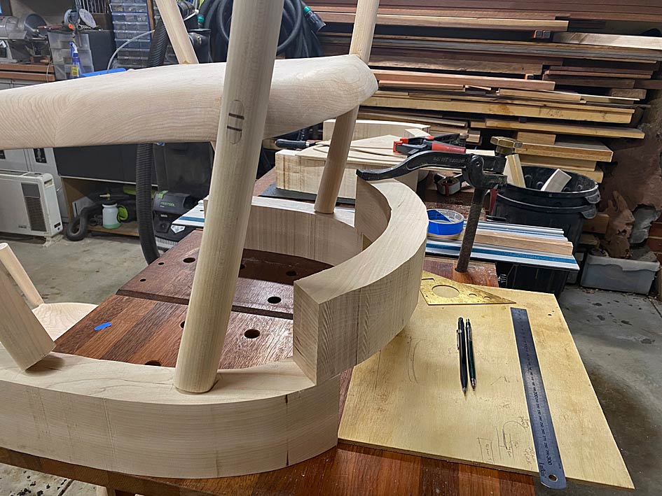
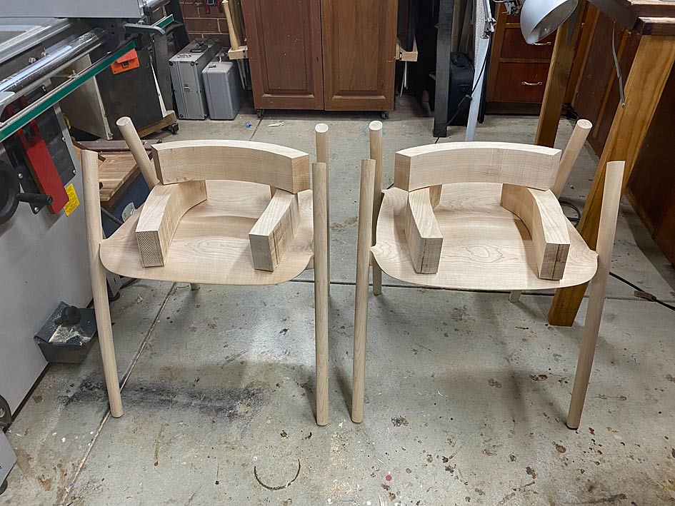
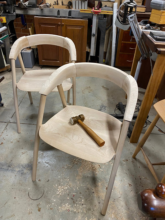
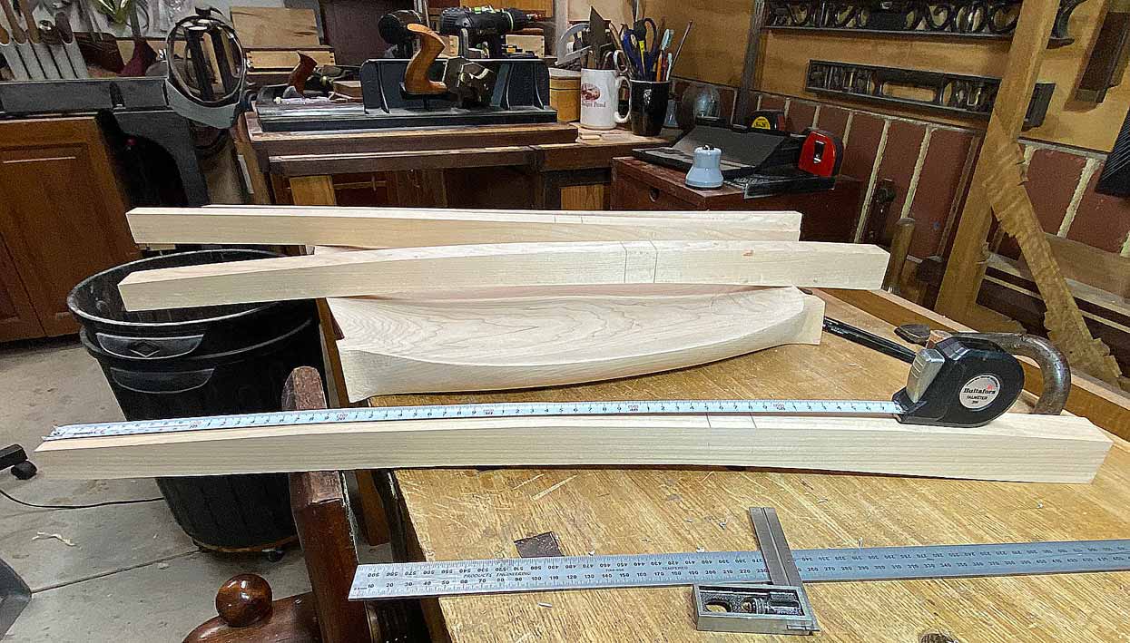
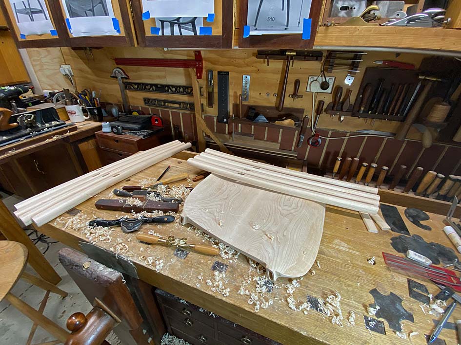
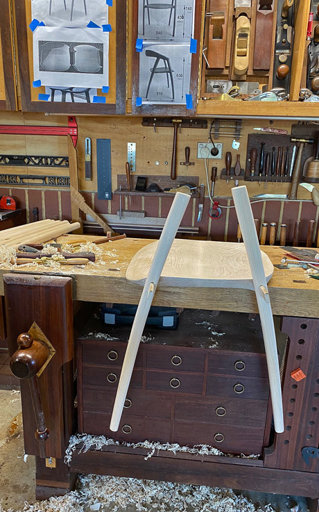
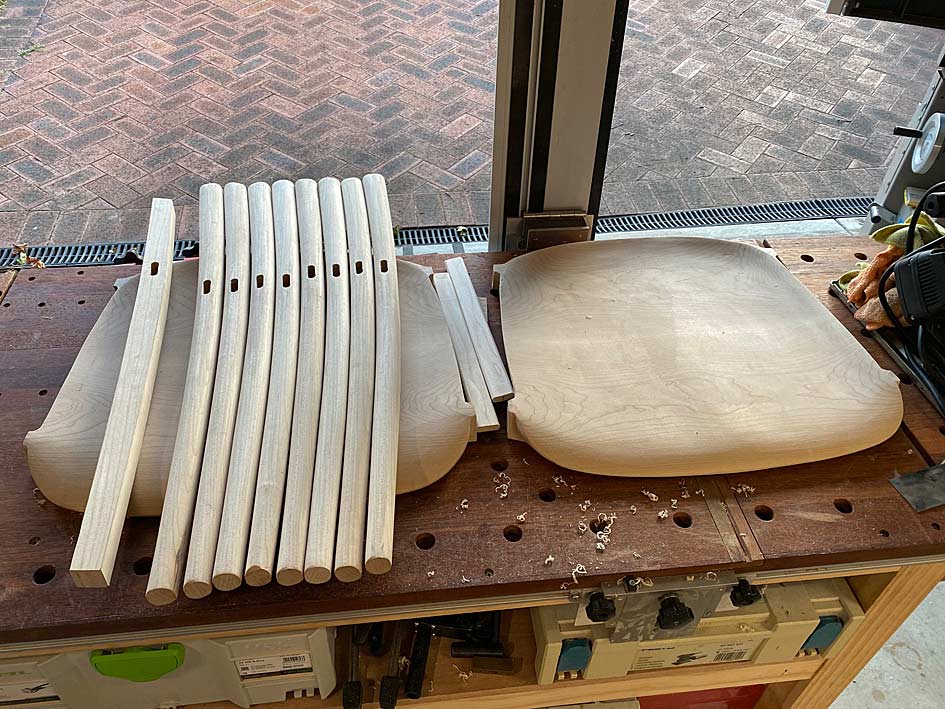
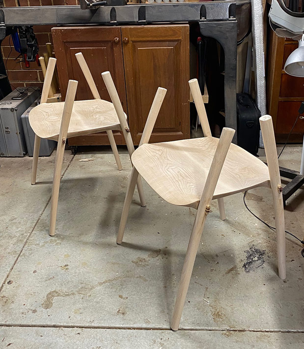
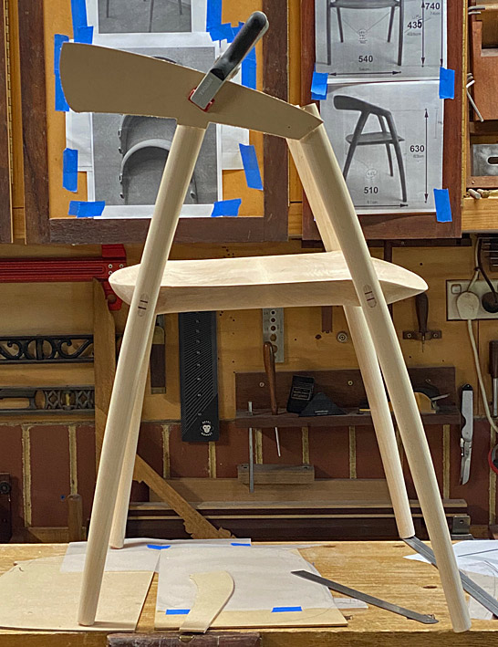
After this was done it became apparent just how the first shaping of the chairs differed from the DC09 design. Here is the first chair along with two legs. In the background can be seen the plan I had made for that build ...
New2.jpg
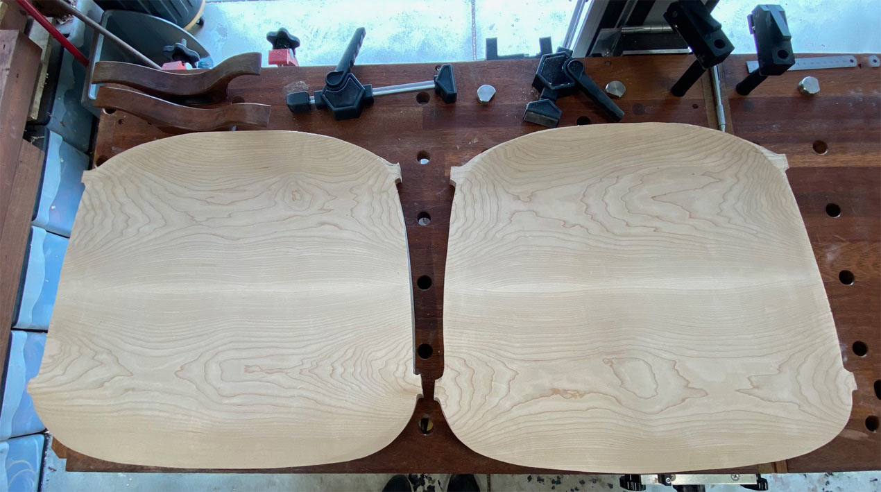
It looks quite good, with the angles and spacings appearing correct. In fact, they are quite different from the DC09. Below is the DC09 seat below the first seat. You can see the positioning of the legs ..
New9.jpg
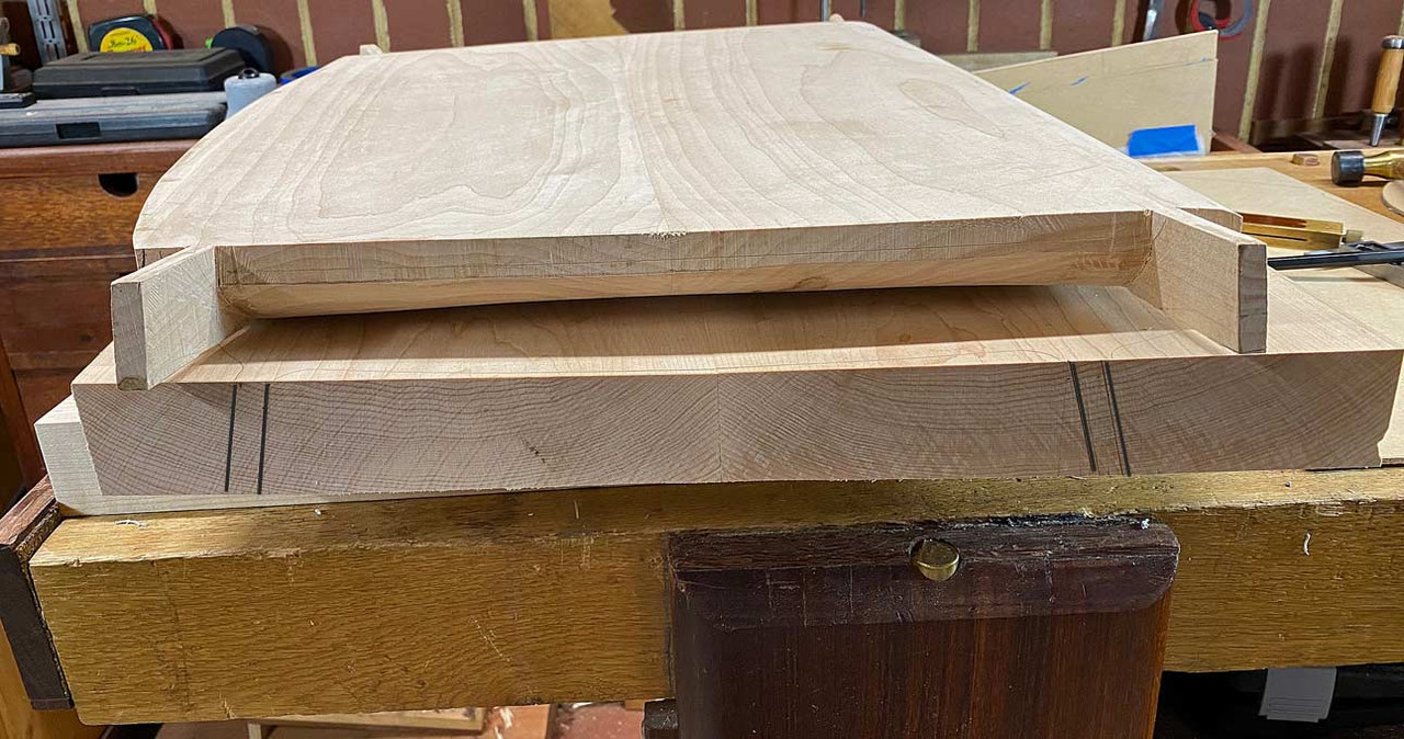
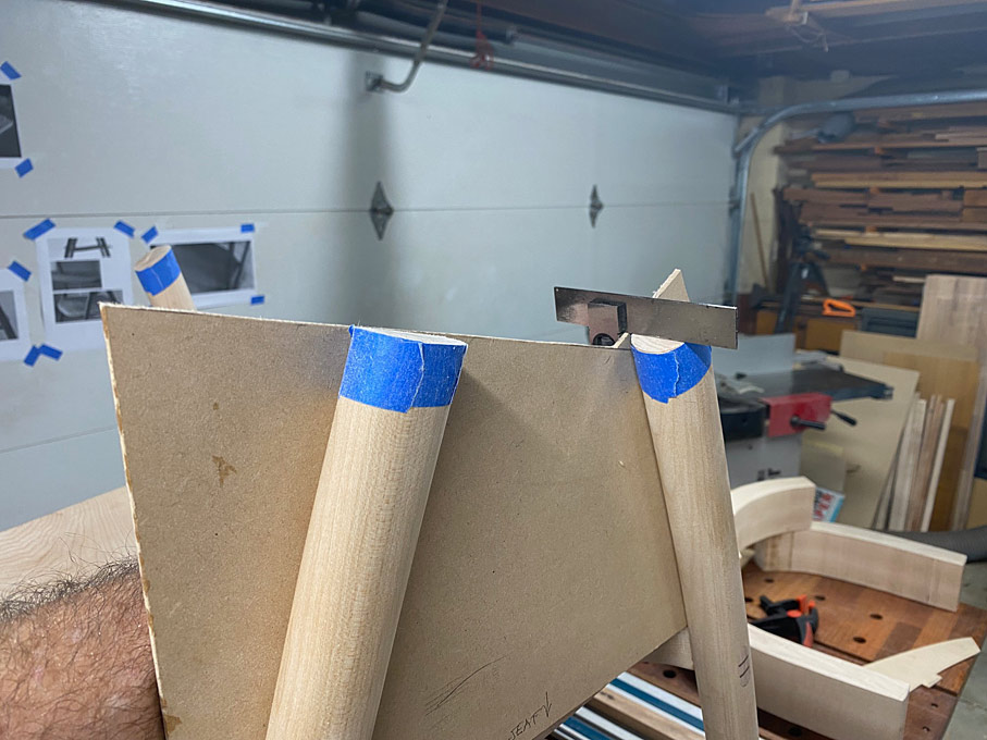
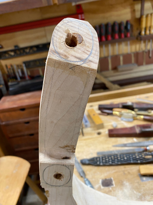
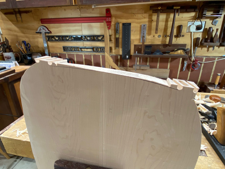
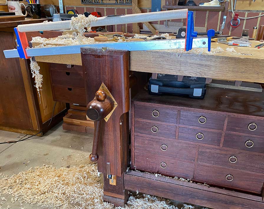
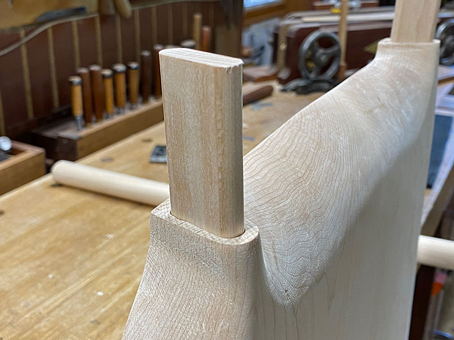
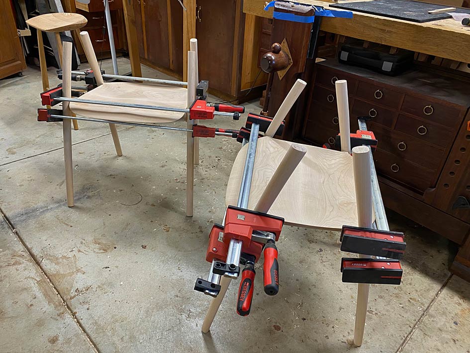
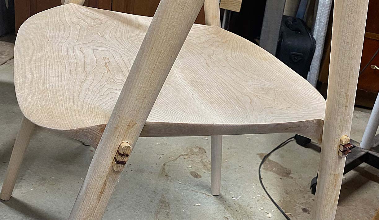
Before I dominoed the mortices, the legs were mocked up to be sure of the angles. I discovered that they should be at 14 degrees and not 10 degrees, as they had been before. In the top right corner you can see a DC09 for comparison ...
New10.jpg
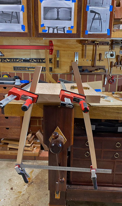
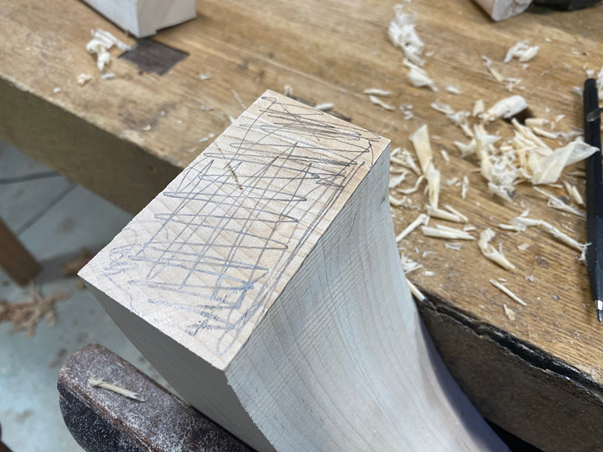
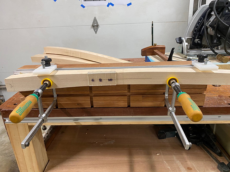
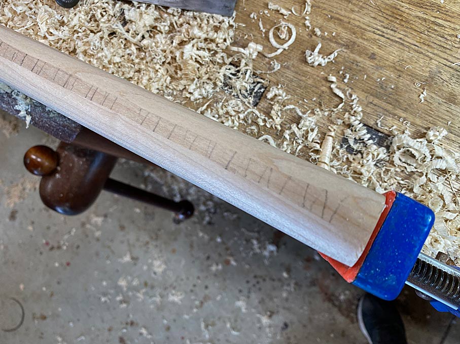
Guides for 14 degrees ...
New11.jpg
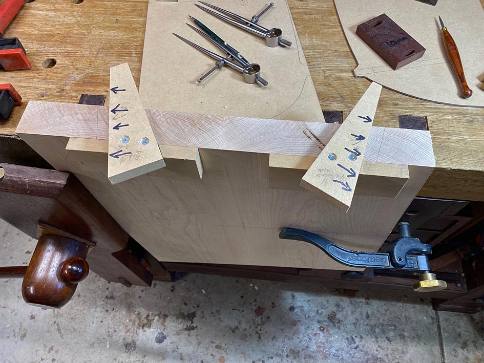
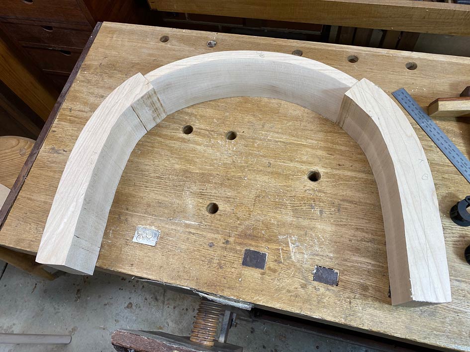
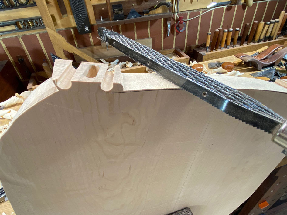
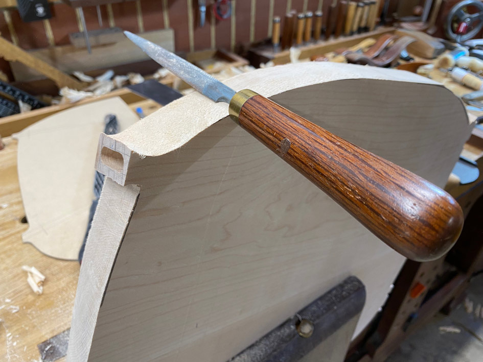
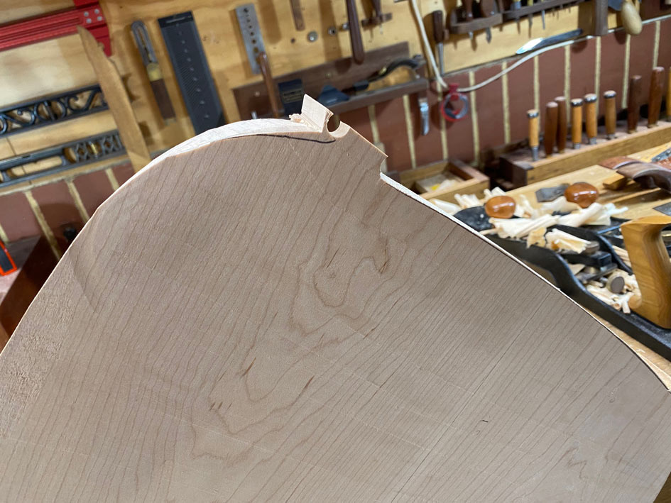
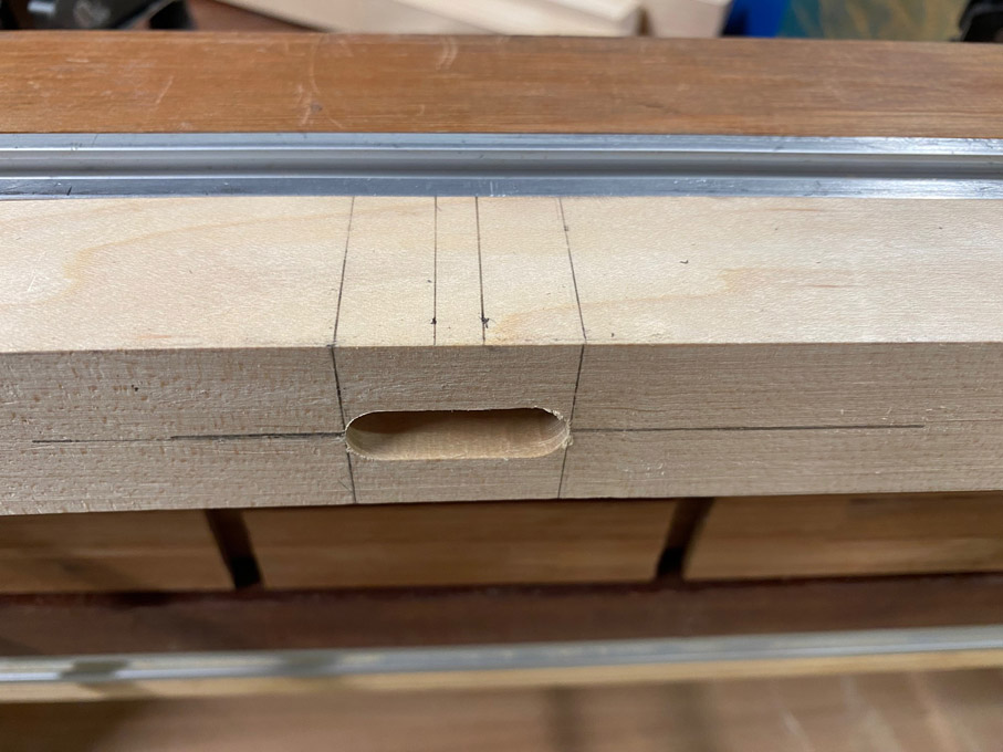
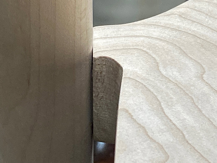
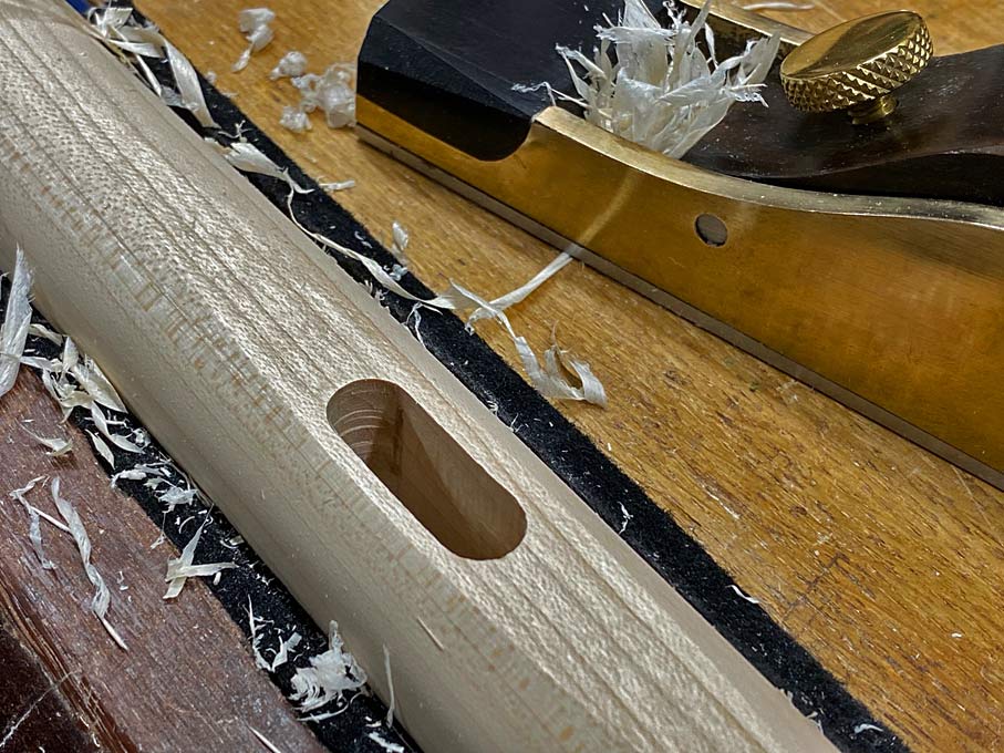
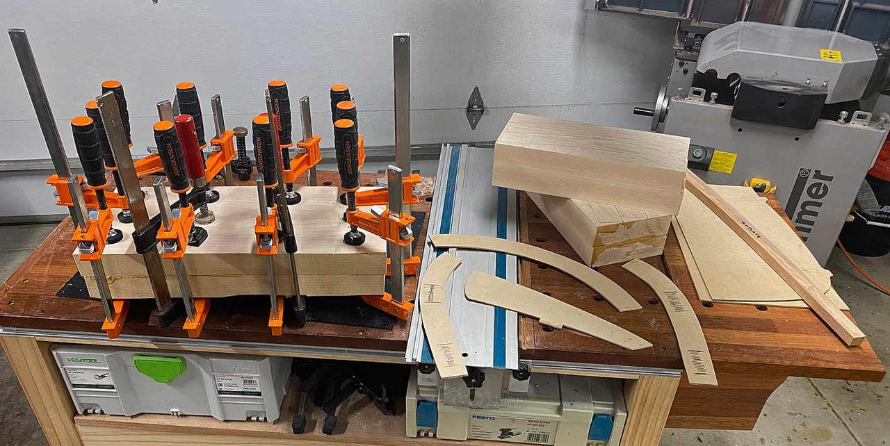
Marked and morticed ...
New13.jpg
New15.jpg
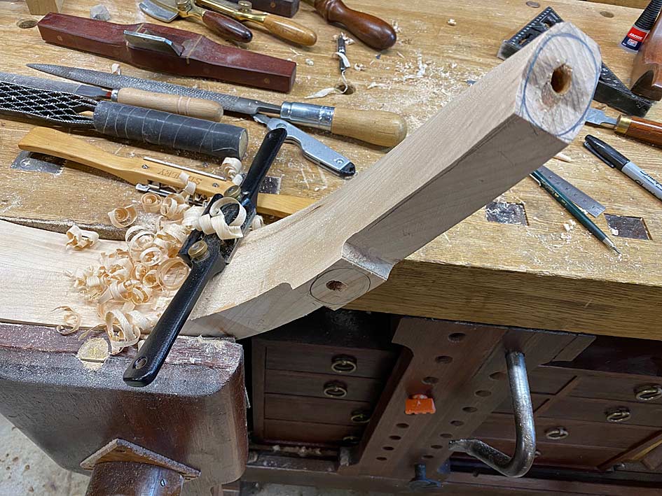
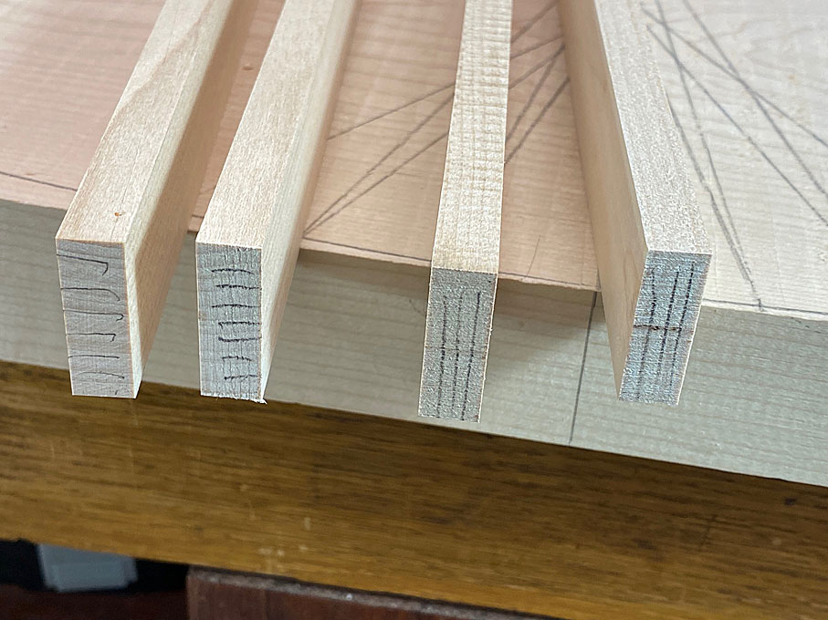
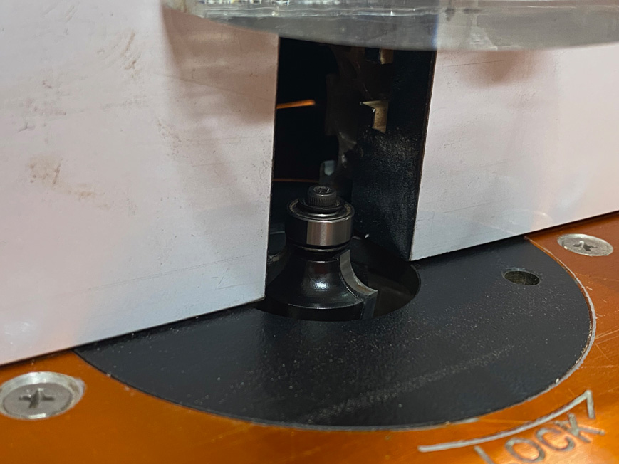
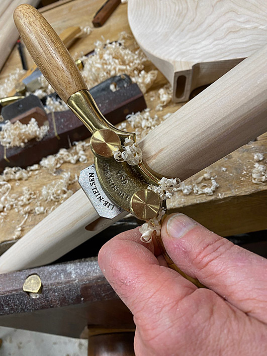
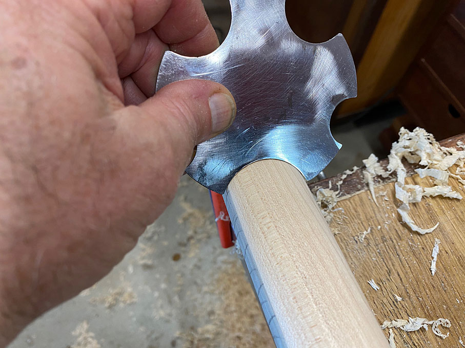
Tenons were made on the router table ...
New14.jpg
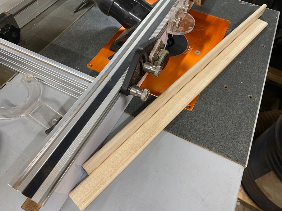
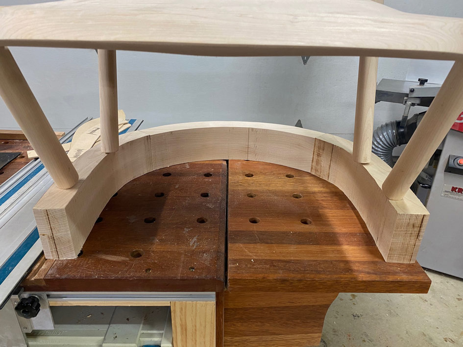
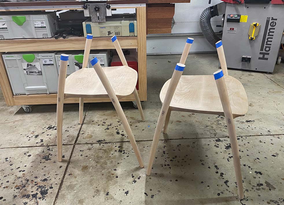
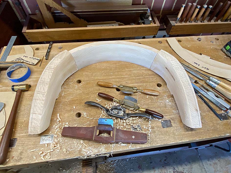
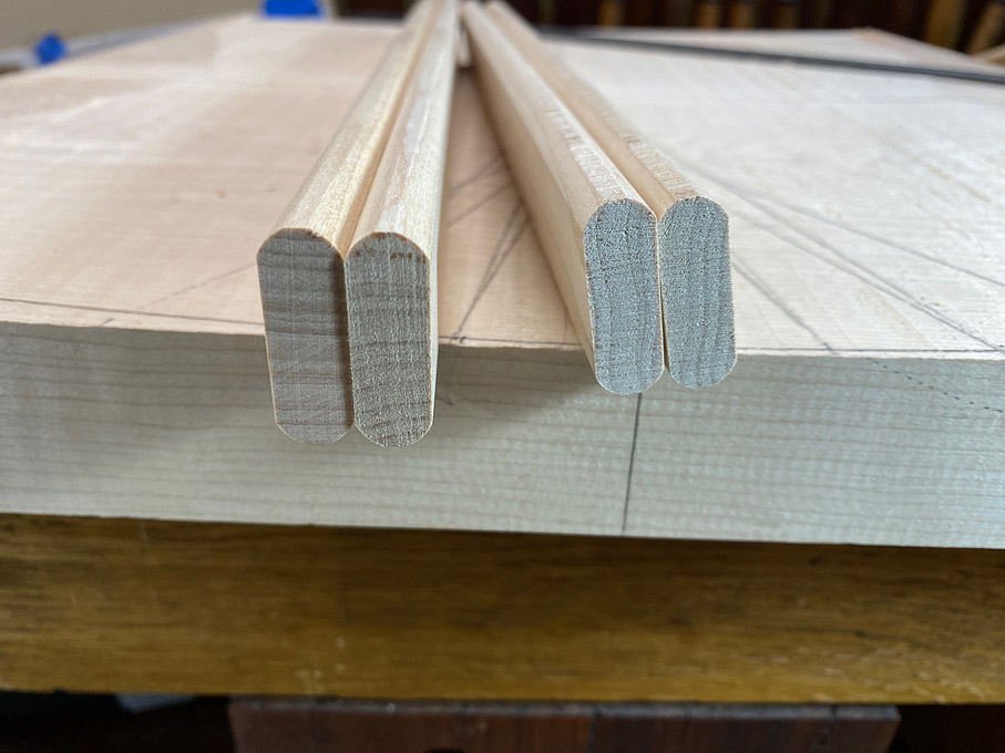
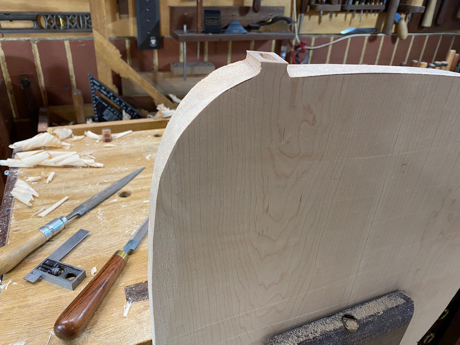
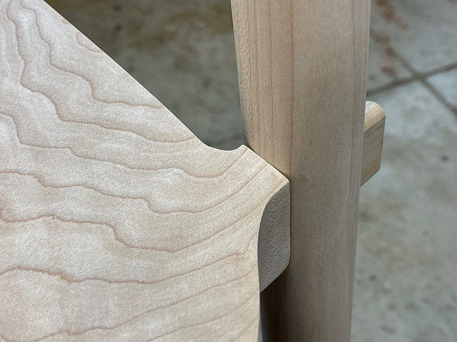
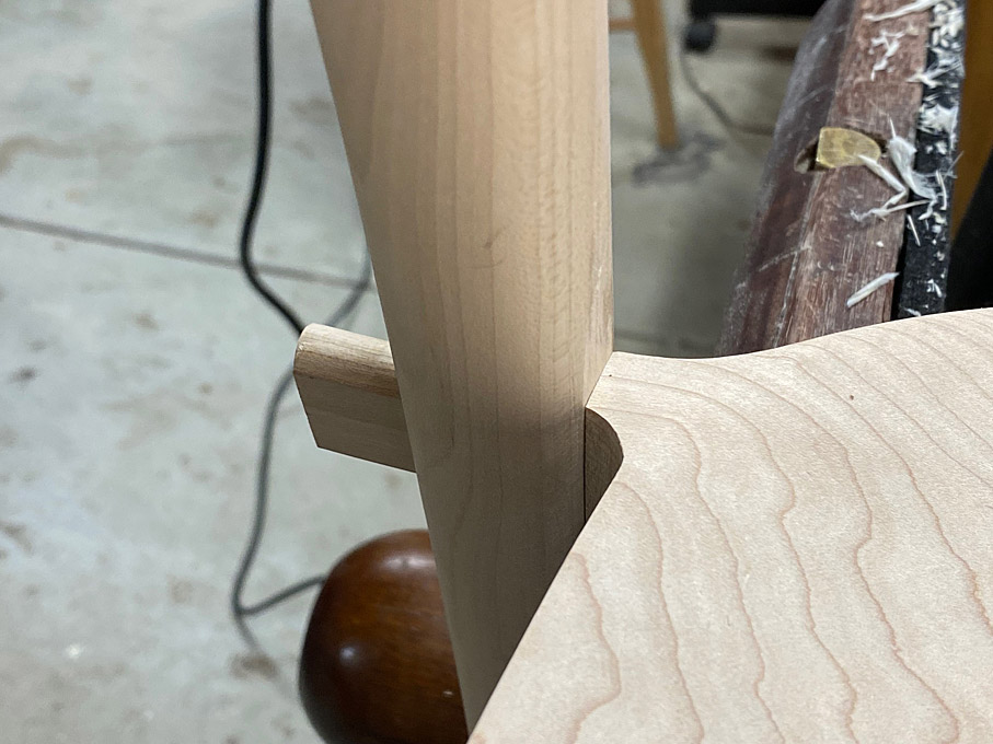
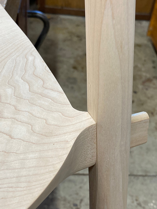
All is looking right so far ...
New16.jpg
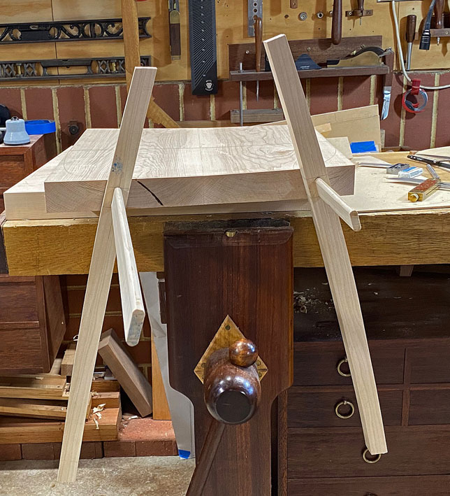
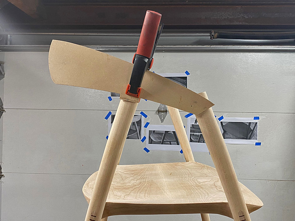
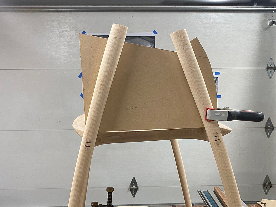
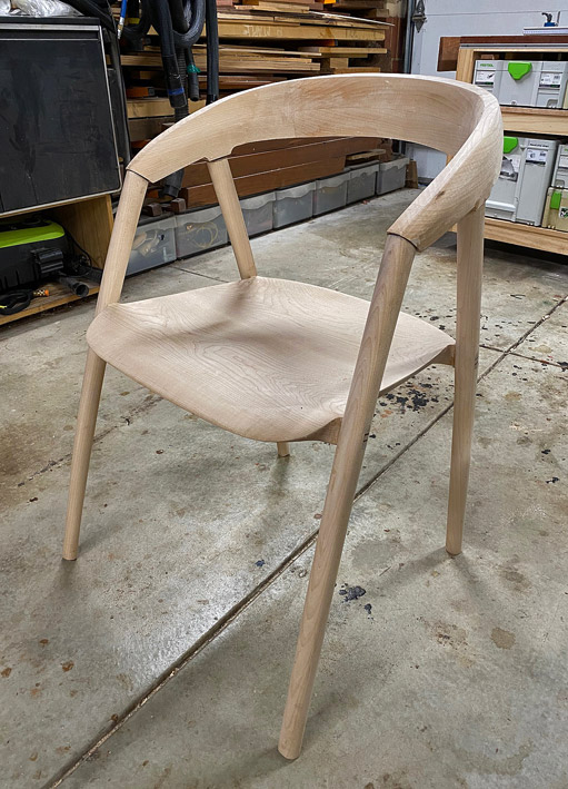
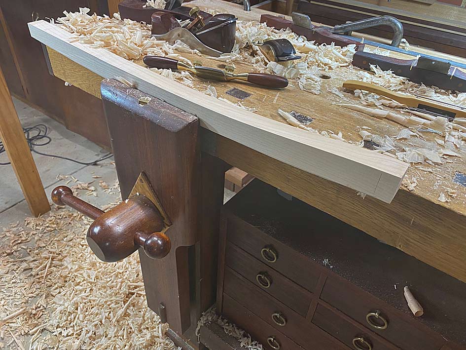
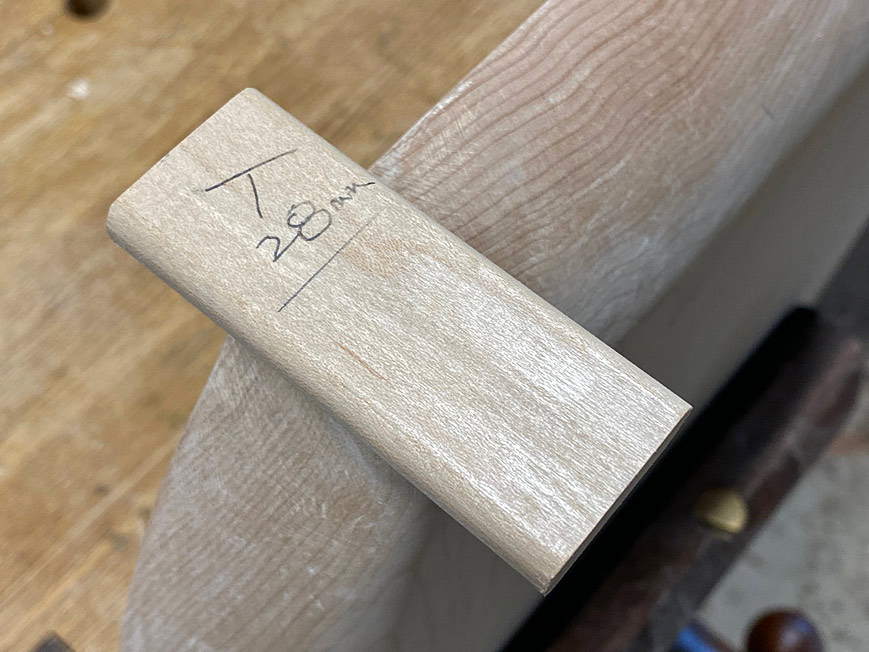
The rule for chair backs is that thy need to allow for a lean of about 90-95 degrees. I have been thinking about this but decided to set aside this area for later. The priority is to get the seat shape correct - in three dimensions. - and its relationship with the legs (which were shaped in the first build - they are substantially correct, other than the upper ends being around 28mm against the - estimated - 40mm of the DC09. I will decide on whether to keep or replace these later). I have left the legs 1" longer in the lower half to adjust the tilt of the seat (the seat sits 18" off the ground and the ones I made previously are 19" in this respect).
I did stand the old chair along the table, and noted how low the arm rests were in reality - actually an ideal height for comfort. I do have some ideas how they may be "improved" aesthetically .... but this for later.

All advice gratefully received.
Regards from Perth
Derek

Added later 9 h 57 min 33 s:


Part 2 - Developing drawings and plans


I was asked how I developed the drawings and plans, especially as there are numerous compound angles. It is a important question for those who want to use the ideas that are around us.

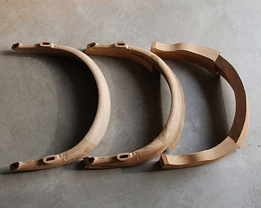
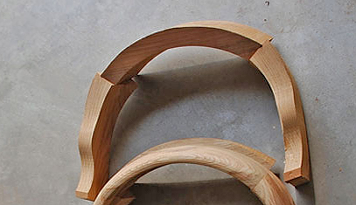
What I do is explore the videos and all photos, and then screen save relevant examples. From this I estimate or calculate size, approximate dimensions, and refine these over multiple examples. Here are some of the photos I used ....
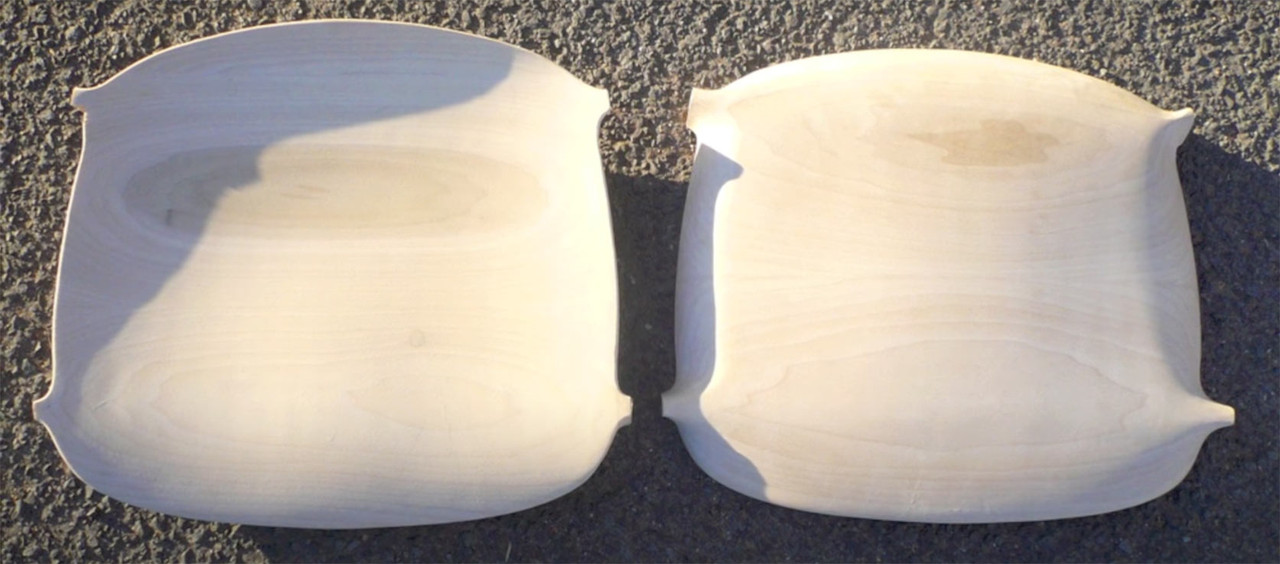
Seats1.jpg

Seats2.jpg

Seats3.jpg

Seats4.jpg

Seats5.jpg

Seats6.jpg

Seats7.jpg

Seats8.jpg

Regards from Perth

Derek

#dc09

Re: Dining room carver chairs - Take 2

#2

Derek, I admire your diligence and persistence. It is wonderful to have all of the pictures available online today but it also takes so much time and effort to find and digest them.

Re: Dining room carver chairs - Take 2

Edited #3

Thanks Gary.  It is part of the fun!

Part 3 - A question about loose tenons

The legs will be joined to the seat with loose tenon mortice-and-tenon joinery. The tenons are Hard Maple, as with the rest of the build. I am in the process of choosing the stock for the 10mm wide x 30mm long tenons. The aim is to ensure that these are the best for a chair. Not any other purpose, but a chair.

The issue is grain direction: is it better to have the grain running horizontal or vertical?

Tenon1.jpg

Vertical grain should offer more rigidity, while horizontal grain more flexibility. While is preferred - your opinion?

The square stock is shaped on the router table ...

Tenon2.jpg

Tenon3.jpg

This is how it will look in the leg through mortice (minus the wedge and the rounded leg) ...

Tenon4.jpg

Regards from Perth

Derek

Added later 6 d 1 h 31 min 16 s:

Part 4 - Carving the seats


This is a long post with a good many photos. Treat them like a comic strip - flip by. It's just that there is so much more than one might realise that needs to get done when carving a seat. It is a 3D construction, and more complicated than joining square sections. This will become apparent as we progress.

These are the two seats. Both have been prepped with drilled holed to carve to depth. My plan is to work two seats alongside one another, completing a section on one and then duplicating it on the other, moving on, back-and-forth. The first stage is to power carve the rear of the seat using the Arbortech ...

Build1.jpg

Build-dots.jpg

Garage doors make for a handy white board to hang photos. These are the seats, and the angles provide the needed guidance.

Buil2.jpg

First shaping ..

Build3.jpg

It's rougher than it looks. A travisher begins the process of smoothing the curves ..

Buil4.jpg

Every now-and-then a scraper will refine the tear out ...

Build5.jpg

We begin the front section of the seat now, again using the Arbortech carver ...

Build6.jpg

And refine with a travisher ..

Build7.jpg

... always feeling the surface with a hand to detect any uinevenness ...

Build8.jpg

It is beginning to resemble the photos ...

Build9.jpg

At this stage it is time to cut out the seat surround, but before this can be done, the mortices (for the loose tenons) need to be preserved. This is not straight forward as they angle at 14 degrees. As a result, it is not possible to saw from end to end. The area around the tenon will require extra shaping.

My plan was to drill alongside the base, which would refine it and also create a curved root ...

Build10.jpg

Build11.jpg

Then as much as possible was sawn away with a jigsaw ...

Build12.jpg

Time to refine the front section and tenons. To do this, the underside of the seat needed to be made perfectly flat: this will provide a reference side to mark the boundaries at the front for carving to; also, taking down the bottom will define the bottom of the tenons ..

Build13.jpg

Build14.jpg

The shape of the underside is estimated using the templates for the top side ..

Build15.jpg

.. and refined with a rasp ..

Build16.jpg

Waste sawn away ...

Build17.jpg

.. and shaped ...

Build18.jpg

Again and again ...

Build19.jpg

Build20.jpg

Finally the front of the seat can be shaped as it flows from the end of the tenons ...

Build21.jpg

With raking light, the tear out and bumps are more easily seen, and now sanded down with 80 grit (more will be done much later on) ...

Build22.jpg

Build23.jpg

And that's it for today. Underside shaping to come.

Regards from Perth

Derek

Re: Dining room carver chairs - Take 2

Edited #4

On the grain orientation I would arrange the growth rings vertically to align with the long axis of the leg. As you show with the test tenon peeking through. Although it probably doesn't matter much, I'd argue a slight advantage in have long plates of harder, denser late wood oriented vertically rather than short stretches stacked. I think the former orientation would resist shear better.

It is an interesting question, though. I don't think I've ever seen it discussed anywhere.

Thinking about it some more: there may be a greater tendency for the tenon to split if you  drive the wedge between the growth rings rather than across them. That would also argue for orienting the rings vertically.

Re: Dining room carver chairs - Take 2

Edited #5

Part 5 - Completing the seats


Time to finish the seats ... sort of ... well, very close.

This is where we start - two seats completed on the upper side ...

Build33.jpg

Looking at the seat blanks from the side, it is apparent that they are 2" thick ...

Build34.jpg

... and they need to end up looking slim, like this ...

Build40.jpg

Clearly, there is a great deal of waste to remove from the sides. That is, not to thin the thickness, but to taper the sides to create the impression of thinness.

Here is another view, which better illustrates this ...

Build45.jpg

The MFT makes a good bench for carving ...

Build35.jpg

Lines are roughly pencilled on the seat and then the Arbortech is used to carve away as much waste as possible ..

Build36.jpg

I relied on a Auriou 10-grain rasp to do most of the shaping ...

Build37.jpg

... until I was loaned the largest rasp I have ever seen. Large enough to cause most here rasp-envy. It says Nicholson on it, but it appeared larger than a Nicholson #50, and far, far coarser than the 11-grain it is advertised as having. Any ideas?

Build38.jpg

I moved between rasps and spokeshaves to shape and smooth the curves ..

Build39.jpg

To be frank, I worked without a specific plan other than to create fair curves - the curves almost decided what waste to remove, while I monitored the photos I had for reassurance.

In the end, with everything sanded to 80-grit, this was the result. From the underside ...

Build41.jpg

The upper side, from the rear end ...

Build42.jpg

And side ...

Build43.jpg

And one more photo, taken at an angle similar to the "slim line" view above ...

Build44.jpg

There is still work remaining in the seats: every time I look at the chair photos new details become apparent. So I shall get on with the legs, and return to fine-tune the seats later.

Regards from Perth

Derek

Added later 7 d 18 h 19 min 39 s:

Part 6 - New legs


Every time I sit down to write up the progress made I feel like apologising for how little there is to show for the efforts made. I have made this observation before - it is tough to copy from photos when there are no measurements to follow, but it is especially so when the piece is curved and changes shape from different angles. I keep finding new detail to add in, and it seems like a never ending carousel.

One example, the front underside of the seat is concave and not convex. I added this, but need to do more ...

L1.jpg

The seats need quite a bit more work, mainly refining details. For example, the sides need to be tapered more. For later.

For now I return to the legs.

I did make 8 legs when building Mark 1 of the chairs, but now I am about to re-make them completely. Why? Because the first set of legs were designed for a chair which was inspired by the DC 09 Chair, but now that I am attempting to get close to this design, the legs also need to be in keeping.

Step one was to create a template, and then mark out 8 legs. These were bandsawed close to the lines, and then cleaned up with spokeshaves ...

L2.jpg

The second time around is always easier, and marking out the mortises was much more efficient by measuring the front of the legs ...

L3.jpg

... and then dropping the verticals ...

L4.jpg

This is made possible by ensuring all sides were kept square when the leg blanks were made.

As before, the Domino was used to mortice the through tenons. The legs are clamped to a mortising fixture.

L5.jpg

The mortises are 30mm long and 10mm wide, and through the 30mm thick legs. Since the Domino 500 can only rout to a depth of 28mm, it was done by working half way from each side.

The mortise needed to be marked very accurately, and to do this I used a marking jig I developed and wrote about recently ...

L7.jpg

The article is here:  https://www.inthewoodshop.com/Powered%20Tools%20and%20Machinery/DominoDW500AsAMortiser.html

It was possible to be as accurate as this for both sides and all the legs ...

L6.jpg

This ended with a pile of legs blanks plus mortises ..

L8.jpg

Early on in the build of Mark 1, I attempted to use a half-round bit on a router table to round the legs. This was a disaster as the Rock Maple blew up, leaving me with wet trousers. Looking back on this sad experience, I realised that I had literally bitten off more than I should have chewed. So I was determined to try again, but this time rout in stages, little-by-little ...

L9.jpg

The leg at the rear is one I attempted purely with spokeshaves. It was a miserable experience - Rock Maple is well named.

Here are 8 semi-finished legs. The corners have been rounded, but much of the leg is still square-ish owing to the tapered profile - the legs start at 35mm at the top, are 30mm by the mortise, and end at 22mm at the feet. Consequently, there is still a whole lot of shaping still to do.

L10.jpg

Look closely and you can see the flats on the sides.

There followed a lot of spokeshaving.

A progress shot of 4 completed legs and 4 incompleted legs ...

L13.jpg

"Completed" really means "done for now". There is constant refining. Slowly the square becomes less so, and then round, but with imperfections, and then eventually there are just fine tracks ...

L11.jpg   

I must admit that it is so tempting to leave it like this, where fingers can caress the tool marks ...

L12.jpg         

This would look better on a different style of chair, and the DC 09 is better suited to a sanded finish.

Here are two of the legs to gauge progress. Note the photo on the wall in the background for comparison (also recognise that the arm section of the legs has been left long at this stage)...

L14.jpg

L15.jpg

Until next time.

Regards from Perth

Derek

Added later 6 d 1 h 28 min 08 s:

Part 7 - From Rectangles to Oval


When I began this build, I looked at the legs of this chair and recognised that they were curved, tapered and oval. Well, oval at the top and round at the bottom ...

Chair2.jpg

I wasn't sure how to do this - the tapered oval shape. I just accepted that I would discover this as we went along.

I began by shaping the legs in profile and cut the mortises ...

L8.jpg

Then knocked off the corners with a round over bit. The leg at the rear was an attempt to do all with just spokeshaves - not great. The round over provides a helpful guide ...

L9.jpg

This left them rectangular with rounded corners. This weekend the rectangles became tapered ovals.

Working at the bench, holding the legs in a clamp ...

LL1.jpg

The first step was to cover the legs in pencil scribble. The purpose here is to make it easier to see where I am working. This Rock Maple is so light in colour and difficult to pick up details.

LL2.jpg

LL3.jpg

Some of the waste had already been removed by spokeshaves, but now the final shaping needed to take place. The tools used were a convex spokeshave and a set of convex scrapers - different sizes.

Once sharpened, the scraper make nice shavings ...

LL5.jpg

The scrapers also provided a template for the curves to be retained on the legs. The taper on the sides of the legs goes from 40mm at the top to 30mm at the mortice to 25mm at the feet. The edges (facing forward and rearward) is a uniform 30mm. So this meant that there was a single convex scraper for the edges and two scrapers for the sides.

This is the difference between a scraper and the leg ...

LL4.jpg

Running it along the leg reveals the low section through the centre ...

LL6.jpg

As you work down, so the curve increases, and the high spot gets smaller ...

LL7.jpg

The convex spokeshave helps out ...

LL8.jpg

Also, angling the scraper allows a wider cutter to follow the outline of a narrower section ...

LL9.jpg

Eventually, the scraper and the leg share the same profile ..

LL10.jpg

LL11.jpg

Lots of work on a very humid weekend. All legs completed now ...

LL12.jpg

Regards from Perth

Derek

Re: Dining room carver chairs - Take 2

#6

Benham_Design

This was a really well thought out design, as well as well researched.

Re: Dining room carver chairs - Take 2

#7

Derek: It's hard to conceive how someone in this day and age of instant gratification could accomplish what you doing. Even if I had the skills (I don't), I have the attention span of a gnat and would never attempt anything close to those chairs. Nonetheless, it's inspiring to see what you are doing. Thanks for taking the time to post.

Re: Dining room carver chairs - Take 2

#8

Thanks BD and Pat

I must admit that this is an unusual build for me. I literally do not know what I am doing ... insofar as I have to keep returning to parts to refine and refine them. That is what is so time consuming. I don't always score high on being sensible, but I do on perseverance and being bloody minded!

Today was not a work day, and I ear-marked completing the seats. The upper side was 99% done, but the underside needed fine-tuning. I have two photos to guide the shaping ...

Seats1.jpg

That one (above) is from the factory building the prototype. They screwed the legs to the seat, rather than use integrated tenons. This proved to be a great model in my case.

The second photo is a production chair seat taken from the underside. In particular, this shows the treatment of the smoothing of the tenons and their integration with the back ...

Seats2.jpg

Lastly, I keep returning to this photo of the chair, which shows how thin the seat looks from the side. Keeping in mind that the seats started out at 50mm, and were 40mm after the plan was cut out, a great deal of tapering was necessary to achieve this look ...

Build40.jpg

Here are the two completed seats. The seat on the left is face up, and the seat on the right is bottom up ...

Seat1.jpg

Regards from Perth

Derek

Re: Dining room carver chairs - Take 2

#9

Wonderful achievement, Derek!  I would have loved to see you use a draw knife on the bottoms and legs to remove the bulk of material.  When razor sharp they are easy to use,  P.

Re: Dining room carver chairs - Take 2

Edited #10

Hi Philip

A drawknife just was never the right tool. Too coarse for what was needed. 

After the leg blanks were marked out with a template, they were sawn out on a bandsaw, where about 1mm waste remaining to be removed to the line. The spokeshave was a better - more precise - tool for this job ... especially in Rock Maple.

Regards from Perth

Derek

Added later 1 d 21 h 28 min 20 s:

Part 8  - Glue up


Today we reached the milestone I was patiently (okay, not so patiently) waiting for - glueing up the legs and seats. To get to this stage, however, required matching the mortices with the loose tenons, matching the loose tenons with the leg mortices, cutting slots for the wedges (into the tenons), and shaping the tenon mortise to fit the legs.

Let's start with the obvious. This is how the tenon and the tenon mortise will end up looking ...

T2a.jpg

The loose tenon is 30mm wide and 10mm thick. It extends 28mm into the tenon mortise ...

T3a.jpg

This all looks rather neat, but it was the end result of further shaping to fit the legs with the seat. The issue was that the seat mortices were chunky ...

Seat1.jpg

When joined, this was the fit ...

T4a.jpg

T5a.jpg

Two steps were involved. Firstly, the tenon mortise was reshaped to be thinner at the face (this involved removal of waste at the top edge and not the sides, which is needed support for the loose tenon) ...

T6a.jpg

Secondly, the face of the leg mortise was planed flat to match the face of the seat mortise ...

T7a.jpg

This is how the original chair was fitted - photo I posted early on ...

Seats3.jpg

This is the result ...

T8a.jpg

T9a.jpg

All the parts fitted, but not yet glued up ...

T10a.jpg

Loose tenons slotted for wedges, along with the wedges. Glue of choice: Old Brown hide glue. Why? Because at some stage in the future, hopefully many years from now, it is likely that the joinery will need to be re-glued.

T11a.jpg

The seat tenons are glued first and the glue allowed to dry (they are a bit long here, and were cut shorter before the legs were attached) ...

T12.jpg

And a last photo of the final glue up. It will remain so for 24 hours.

T13.jpg

Starting to look like chairs!  ;)

Regards from Perth

Derek

Added later 1 d 11 h 06 min 26 s:

A Note about Wedges


This is a cross post from the Australian forum, where I was asked for more information about the wedged through tenons.

I am not sure if the photo provided must detail, but the wedges are tapers, but also long and skinny ...

T11a.jpg

They both fill the slot - which is full of glue - and create a wedging action, firmly pushing the tenon edges against the glued insides of the mortise. The mortises, both in the seat and legs was 30mm long. Most were exact, some of the legs were a little under a mm long. A little filing for all to create this tiny gap - it does not have to be more. The glue is enough and the wedges are security. Interestingly, this appears to be the same in the original chair, with the exception that they added a chamfer for the end of the wedge. I've never seen this before ..

Chair-seat5.jpg

In addition to the wedged legs (I am trusting that the small amount of taper inside the mortises will add an extra layer of solidness), the arm/back structure adds stiffness and resists the legs wracking/moving. It is akin to triangulation of the construction (not really triangles, of course).

I have removed the clamps and the structure is really stiff already - I will wait until Lynndy is out of the way to take some photos. She-Who-Must-Be-Obeyed is keeping a steely eye on my "taking it easy" today! anoyd.gif  [Explanation: I was in hospital yesterday for an op on my left torn patella]

Later: 

I snuck into the workshop to unclamp the glue up. Lynndy caught me! But she then asked to sit on one of the chairs (sans the arms and back). She did so gently, and then with all her weight (55Kg). The seats did not even sigh, and nothing moved. She proclaimed the seat very comfortable. Yay!

Tenons and wedges yet to be cut and levelled ...

T15.jpg

T14.jpg

Regards from Perth

Derek

Added later 11 d 7 h 57 min 38 s:

Part 9 - Beginning the arms and back


The legs and seats are done and it is time to move to the arms and backs. Once again, the chair to provide a context of where we are headed ...

Chair2.jpg

I was fortunate to find a few photos on the Web showing the development of the arms/back, which provided some insight into how to construct this ...

Seats4.jpg

The construction sequence that was really helpful was this (note these are from the underneath) ...

Arms1.jpg

While this makes it all appear accessible, my experience building a Hand Wegner chair prepared me for the large chunks that make up the two arms and the back ...

TheChairShapingArmsBackPart1_html_m11f0c459.jpg

Giant slabs and lots of carving (since, unlike the factory, I do not have a CNC machine) ...

TheChairShapingArmsBackPart1_html_m2b87da0c.jpg

But look at the first photo in that sequence - the back is angled into the arms. Wonderful - less to carve!

Arms2.jpg

The arms need to be shaped from blocks 90mm high, so I got busy laminating ...

Arms7.jpg

And while this was drying, time was spent on getting the profile for the side of the arms ...

Arms3.jpg

There's a photo on the wall behind against which to compare. Also, a first look at the completed through tenons.

That's the easy stuff. Time to design the arm and back profiles.

We start with a seat ...

Arms8.jpg

... to use to frame around ...

Arms9.jpg

After much back-and-fro drawing, rubbing out, re-drawing, and transfering to MDF for templates ...

Arms10.jpg

Each of the blocks (seen beng glued up earlier) create four arm blanks ...

Arms11.jpg

Here is the side elevation ...

Arms12.jpg

Wood for the backs came from sawing up this 3m long board ...

Arms13.jpg

And, for now, the backs are laminated and drying alongside the other blanks and templates ..

Arms14.jpg

Tomorrow I shall begin cutting it all up, and joining pieces together.

A question for all is how you might connect/join the arms with the legs? Note that the back will be joined angled to the sides, as per the photo.

Regards from Perth

Derek

Added later 1 d 07 min 12 s:

Part 10  -  More on the arm jigsaw


Here is the work done today, which was preparing the arms before shaping. Critical work, and the day went well. This was mainly due to working methodically. Looking back it all seemed so logical and straightforward, but it didn't feel this way before hand.

The first task was to bandsaw all the blocks of wood into shape, having outlined the parts with the templates.

Arm1.jpg

Lining up the arm parts for two chairs, three for each ...

Arm2.jpg

At first I thought I would clamp them together and balance the lot on top of each chair ... no, that would be silly! :)  
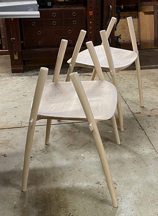
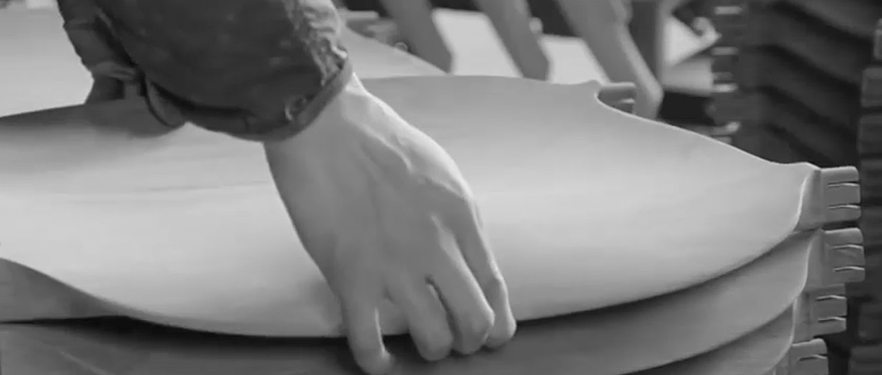
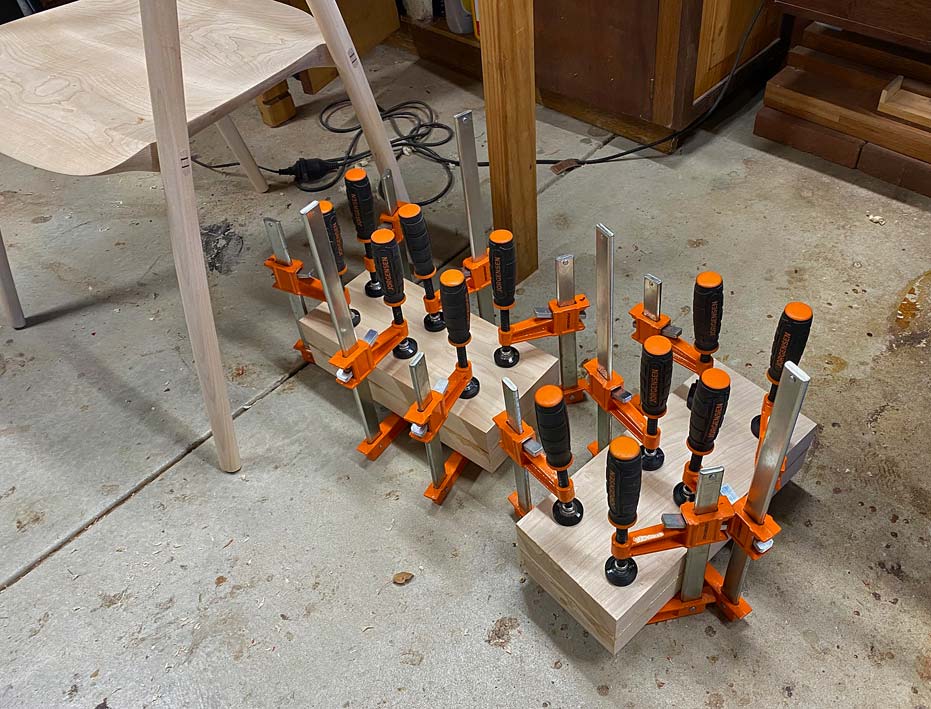
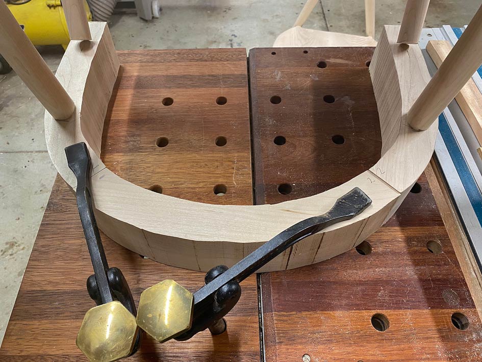
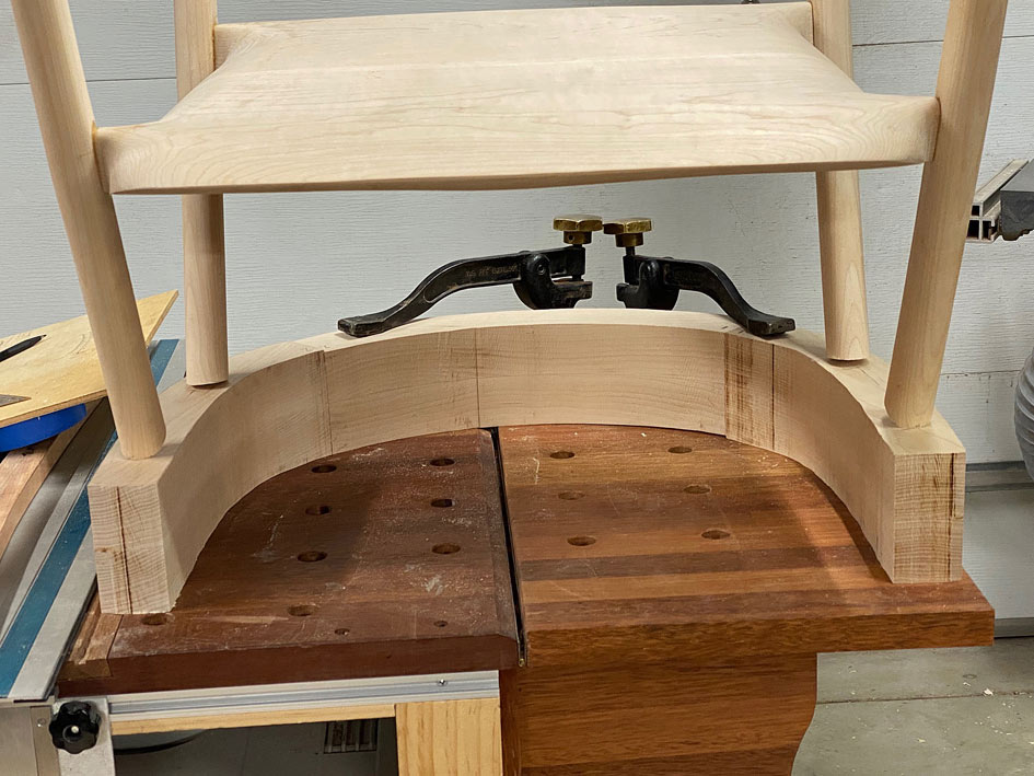
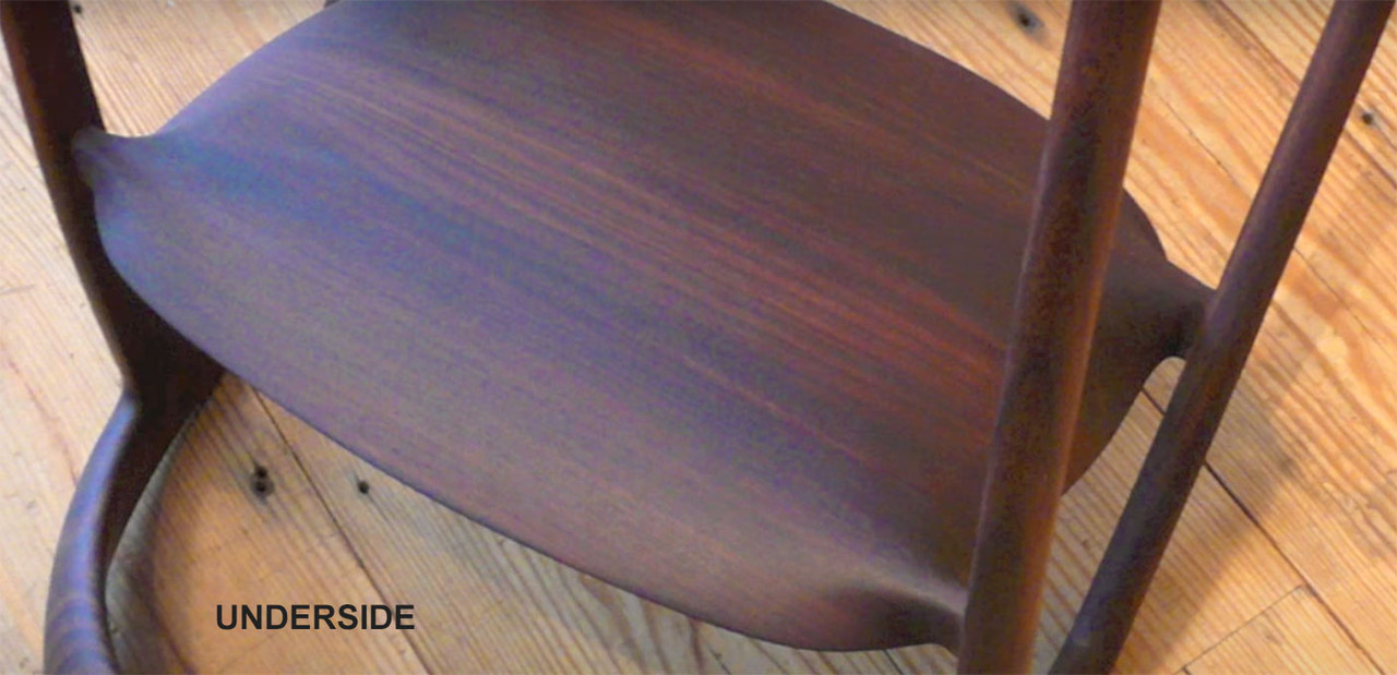
The chairs were turned upside down on the arms ...

Arm3.jpg

This revealed that the spread of the arms was a little too wide. The arm supports need to be centred on the arm rests ...

Arm4.jpg

Before adjusting this, the next stage needed to be to cut the arm supports to length. To do this, first the template for the arm elevation was positioned ...

Arm5.jpg

... and then a template was made to position this ...

Arm6.jpg

This allowed all the arms supports to be marked on both sides ..

Arm7.jpg

.. and marked with blue tape ...

Arm8.jpg

The excess is sawn away ...

Arm9.jpg

The template also enables the accuracy of the saw cuts to be checked, and for square. This will need to be fine tuned later, but good for now ...

Arm10.jpg

Arm11.jpg

The underside of the arms are marked so the positions on each will be the same, and the overhang at the rear was roughly calculated. Again, this will be adjusted after the arms parts are joined.

Now the top rail can be positioned for sizing ..

Arm13.jpg

It is marked for sawing ...

Arm14.jpg

Aligned on the slider ...

Arm15.jpg

All the ends of the arms are squared this way, however the saw has a maximum cut height of 75mm and these parts are 90mm. This leaves 15mm to saw away with a hand saw, and then clean up with a block plane. This clean up is important as it is also jointing for the parts to fit together gap-free ...

Arm16.jpg

Arm17.jpg

Arm18.jpg

The arm parts are ready to fit together ...

Arm19.jpg

Arm20.jpg

And all done for the day ...

Arm21.jpg

Regards from Perth

Derek

Re: Dining room carver chairs - Take 2

#11

Derek......you ever make something simple like a bird house or a shelf to hold your salt and pepper shakers??........

Re: Dining room carver chairs - Take 2

Edited #12

Roger, long time no hear!!

But ...... these are just fancy bird houses. Just squint a little and purse your lips ... then you'll see it! :)

Regards from Perth

Derek

Added later 5 d 22 h 20 min 34 s:

Part 11 -  Arms - part 1


The key piece is the top rail, and the key element here is the rear curve. Here it is smoothed on the belt sander. It will be a reference side for marking curves ...

Arm22.jpg

The angles I have had to guestimate have been the tilt, front and rear, of the top rail. This is what I came up with ...

Arm23.jpg

The plan is to join the arms using dowels. The Rule of Thirds applies. 3 x 3/8" dowels (3/8" = 9.5mm, which is close to the 10mm tenons used previously). Why dowels? Because they are easier to position accurately without a reference edge.

Since a large amount of waste will be removed from the top rail and arms, through shaping, the dowels need to be positioned where they will not be cut into. The three marks on the ends of the top rail are the position for the dowels. The wooden block was a quick guide to drill vertical as it needed to be done freehand ..

Arm24.jpg

The only complication was that I had 6mm dowel centre points. It would have been easier if they were 3/8". Nevertheless ...

Arm25.jpg

Arm26.jpg

Drilled for 3/8" dowels in Jarrah (I have a bucket of them), each close to 50mm (2") in length.

Arm27.jpg

Arm28.jpg

Everything is still a rectangle at this stage ...

Arm29.jpg

The inside face of the top rail is shaped ...

Arm31.jpg

It is at this point that I have a re-think about the curve of the rear - it is not a fair curve and enough curve when compared with the photos of the DC 09 chair. The re-drawn curve on the left looks correct to me now, and this is what we will go with ...

Arm32.jpg

Arm33.jpg

The parts are joined up as a loose fit (using undersized dowels)...

Arm34.jpg

The arm/rail combination is now placed on the arm supports and adjusted to the front and rear to determine the rear overhang and position for the front joint ..

Arm35.jpg

The template I made up earlier is used to trace out the side elevations. The shaping here is approximate. The main goal is to establish the length of the arms and from arm support joint ...

Arm36.jpg

A little detail of interest: the height cut is slightly more than the front joint triangle would suggest as the final shaping requires a little extra meat to end in a curve ...

Arm37.jpg

Arm37b.jpg

This is now sawn to shape, except for the underside of the arm, as the mortise/tenon area needs to be determined separately for each arm ...

Arm38.jpg

Tomorrow will begin the final shaping and, hopefully, glue up of the arms.

Arm39.jpg

Regards from Perth

Derek

Re: Dining room carver chairs - Take 2

#13

Absolutely outstanding Derek.  Thanks for sharing.  Way beyond my talents, but I am really enjoying the ride.  I have enough problems with flat work.
  Rpm

Re: Dining room carver chairs - Take 2

Edited #14

Part 12 -  A little more as it is getting closer.


The first step is to align all the arms and mortices ...

Arm40.jpg

There was a lot of scribing, fitting, scribing and more fitting.

Finally the shaping of the underside of the arms was possible as it was now possible to determine the general position of the mortises.

Arm41.jpg

The waste was removed with a bandsaw and coping saw ..

Arm42.jpg

Now the specific position for the mortices was fixed with dowel pointers ...

Arm43.jpg

Drilled and dowelled ..

Arm44.jpg

And the arms fitted to check that all will fit at the end ...

Arm45.jpg

Shaping to come.

Regards from Perth

Derek

Re: Dining room carver chairs - Take 2

#15

Ellis Walentine

I need eight of these to go with the new trestle table I built, Derek. Any openings in your schedule? :)

Re: Dining room carver chairs - Take 2

#16

Derek, I'm curious as to why you shaped the backrest further than you have shaped the arms.  The back rest looks almost finished while the arms appear to be needing considerable additional shaping.  I'm really enjoying watching this build.

Re: Dining room carver chairs - Take 2

Edited #17

Aahh .. Ellis. I think I shall need more time. Can you lend me some?

Regards from Perth

Derek

Added later 01 min 18 s:

Part 13 - The Arms (part 2)


This is a last post before I return from three weeks being dragged over New Zealand mountains by my wife and her family. I used the Easter Weekend to get as much done as possible, but I needed a few more days. So there is more to come, later.

It is helpful to remember what the aim is - as close a copy of the DC 09 chair as possible. All guidance from photos  ...

Chair2.jpg

We left off here ...

Arm45.jpg

The three parts that make up the arms and top rail ..

Arm2.jpg

The top rails were shaped ...

Arm34.jpg

And shaping started on the arms ...

Arm45.jpg

Today the arms were begun.

I find it easier to do one part as far as I can take it, then stop and repeat this with another part. When all four arms have progressed the same distance, I start with the first arm again and take it to the next stage. Then the other three to match. And so on.

Each stage completed must be checked, and this is done by putting the parts together, to check that they balance. The two sides must remain a mirror image, and the two chairs must be identical. There are no templates to mark the lines to work towards, only the rough layout lines that appear fair to the eye.

The arms are shaped with rasps and spokeshaves ... mainly coarse rasps - the Shinto and a 10 grain Auriou - followed with round- and flat bottom spokeshaves. Starting with the inside faces ...

Arm46.jpg

Inside faces mostly done ...

Arm47.jpg

Inside faces almost done, except for the undersides ...

Arm48.jpg

Further along - top inside and outside faces mostly done ...

Arm49.jpg

And that's it for now. More later. Thanks for keeping me company through this build.

Regards from Perth

Derek

Re: Dining room carver chairs - Take 2

#18

Alan Young

A spectacular project and execution of same!

Re: Dining room carver chairs - Take 2

#19

Ellis Walentine

@Derek Cohen (in Perth, Australia),

You're to be commended not only for researching, planning and executing this project -- making up the requisite steps as you go -- but also for the splendid documentation. I recall making projects for magazine articles and having to style and shoot photos of crucial steps along the way. It slowed down progress by at least half, and only a limited number of photos could ever be included in a few magazine pages. Of course, that was in the days before cell phone cameras had become such capable instruments. We have the digital revolution to thank for this amazing ability to document virtually all the steps of a build in nearly real time. 

I wish we could entice more of our visitors to follow your lead. I wish I still had a shop with all the tools and fixtures to build and document more pieces, but time has marched on, at least for me. What remains is the knowledge that, if I really want to design and/or build something, there's always a way. Making do is a way of life.

Cheers, and thanks again. We'll look forward to the final steps in your chair build. What a rewarding project! 
Ellis

Re: Dining room carver chairs - Take 2

#20

Thanks Alan. Thanks Ellis.

I must have been one of those kids who pulled everything apart to explore its inner workings. No doubt I was the bane of my parents' life during my childhood. I have not changed much. It's present in my day job, where I pull apart the minds and lives of others. It's present in building furniture. While I prefer to design my own stuff, there is a great deal of satisfaction in discovering how complex pieces, designed by others, are constructed. In this build I have been continually surprised to discover more detail, exposing the subtleties that came from the designer's mind and hand. 

There is a challenge in reproducing something. One can built a one-off without setting off alarm bells. How could anyone tell if it was not always the maker's intention? Then you make someone's design and are scored on accuracy. Or you make more than one piece of the same design. It is a challenge, and this goes up progressively as the work is no longer straight pieces but involves curves. Curves throw a curve!  :)

Ellis, and all, what was the most challenging piece you have built, and why?

Regards from Perth

Derek

Re: Dining room carver chairs - Take 2

Edited #21

Ellis Walentine

@Derek Cohen (in Perth, Australia),
Ye gods, Derek, the most challenging piece??? I've forgotten more pieces than I can still remember, and they were all challenging in different ways. To me, 'challenging' is a relative term, depending as it does on skillsets, experience, the scale of the project, my evolving design sensibilities, etc.  But, now that you've put me in the Wayback Machine, I'll try to give you an answer...

Probably my biggest furniture challenge was one of my very earliest commissions, back around 1977, coincidentally my first chair design. I had started working with an interior designer in Philadelphia, and he challenged me to build a dining set for a wealthy client -- a table for ten of Brazilian rosewood and white ash, with ten side chairs. There was a further design challenge involved: The dining room had deep-pile shag carpeting, which was popular in those days, so four-legged chairs were going to be clumsy, if not downright unworkable. I won't go into my process of thumbnailing the possibilities, but I finally came up with a lamination tour de force, with a sled base to navigate the carpeting. I built this prototype, shown here in my Florida house lo this half century later. It appeared in Taunton's Design Book Two in 1979. If I had had endless time, I would have done more shaping on all the pieces, but this was as far as I was willing to go.

20230506-001013.jpg

20230506-001057.jpg
The challenge was to construct a form in three-dimensional space to laminate a continuous 9' bundle of nine ash strips into the outer curved frame of the chair. Laminating anything around compound curves is difficult because the strips will only curve in one particular twisting form. It took me almost a month to figure out all the angles, curves, clamping blocks, positioning elements, etc. to do the job. Designing the forms for the other laminated parts took time, too, as did engineering the structure. The main form ended up requiring more than 50 clamps at glue up. Part of the challenge was to distribute the clamping pressure evenly to every inch of the lamination, which meant creating what amounted to a continuous caul by adding half a dozen 1/8" waxed Masonite strips on top of the main laminates during glue up. Here's what that looked like...

image.png

I got the commission and made ten chairs for this customer and six more for another customer in San Diego, then I burned the jigs. Each chair took almost a hundred hours to make. 

For sheer scope of challenge, remind me to tell you about the five-flight staircase in a townhouse, made of black walnut, stainless steel, and custom acrylic. Or any of the houses I built or renovated. It's been a very long strange trip, and every project was about setting the problem and getting it done. Thanks for sending me down the rabbit hole.

Ellis

Re: Dining room carver chairs - Take 2

#22

Alan Young

Ellis Walentine wrote:

I got the commission and made ten chairs for this customer and six more for another customer in San Diego, then I burned the jigs. Each chair took almost a hundred hours to make. 

Holy Cow Boss! 
I read that Johannes Brahms burned many of his scores.  Still-I'm glad you kept the chair!  Side note-  Our whole world of learning/developing/ designing etc will I'm afraid never be the same- as you tubers I see now would never contemplate the idea of this chair let alone how to execute it's production as your clever jigs assisted in the process- Videos would take more time showing the process of making the jigs- as you allude to in your post. 

Beautiful artistry.
Alan
PS  I have started a new thread based on Derek's question re: "What is your most challenging piece?"

Re: Dining room carver chairs - Take 2

#23

Ellis, that twist is a tough one to conceptualise. I assume it was made of steam bent and laminated pieces? And formed similarly to the compound curve of a Windsor settee? 

Regards from Auckland

Derek

Re: Dining room carver chairs - Take 2

#24

Ellis Walentine

@Derek Cohen (in Perth, Australia),

I didn't steam any laminates prior to bending, so the forms had to be shaped per the natural bend that the laminates could take at a given thickness. I worked with a laminate thickness (.088" as I recall?) that was thin enough (in ash at least) to make all the bends I was asking of it. When you get to the point where the force required to clamp the bend is too excessive, you know your laminates are too thick. Unless of course you are somehow willing or able to steam them and press them into shape prior to glue up, which I preferred not to do, if only to avoid introducing too much moisture and possibly affecting the glue.  I used Weldwood Plastic Resin for these chairs because it allows the necessary open time and absolutely resists creep. The only part that got any pre-bending was the tight little parabolic bend at the bottom of the back assembly. For that, I hot-pipe bent the laminates prior to glue up. The heat from the pipe effectively dried out the wood in advance of glue up.

Ellis

Re: Dining room carver chairs - Take 2

Edited #25

Comment on the grain direction


One point I have not drawn attention to, but was important for me, is the grain direction throughout this build. 

If you look at the arms and legs, the grain has all been oriented so that the blanks are quarter sawn. For example, the arms will show the long side grain when looking at them fron the side, as will the legs. The figured sides face the top, are carved away, and therefore the figure is minimised. The aim is to present a clear, uncluttered grain, and this should emphasise the shape/silhouette. This was not possible with the seat, and the figure was positioned as best as possible.

Regards from Perth

Derek

Added later 51 d 16 h 10 min 44 s:

Glueing up the arms


Back on the job after 3 weeks hiking mountain trails in the South Islands of New Zealand, then returning home with Bronchitis (although I was wearing a mask on the plane, passengers preferred to sit with the crying babies than listen to me cough and wheeze!). A few more weeks to recover. First day in the workshop this weekend.

First task was to glue the arms sections together. You will recall that they are reinforced with dowels.

Arm33.jpg

In a similar build, where the sections needed to be clamped together, it was possible to leave "ears" as the blanks were wider/thicker. I could not do that here, and so decided to epoxy these ears on ...

Arm50.jpg

Well, it wasn't particularly successful, even allowing for 24 hours cure time. The ears broke off.

All I could do was clamp the ear on, and pray this would hold.

Arm51.jpg

Later I realised that the problem was that the dowels I used were too tight, and the force needed to drive them home was unexpected. Lesson learned for all - if using epoxy, which is gap filling, the dowels has be a slip fit rather than a force fit. Of course, it would have been easier if I had known this beforehand!

Arm52.jpg

Once all was together, now in one piece (or two pieces if you count two chairs), the rasping and spokeshaving began ...

Arm53.jpg


Arm54.jpg

The aim now was to get the arms closer. This is all slow work, a bit here and a bit there, return to check the symmetry and shaping, and a bit more off. Work stopped to redrill the dowel holes that hold the arms to the legs. There had been a little movement while I was away, or I have measured inaccurately the at the start. It is important that the arms-legs join with as little stress to the joint as possible.


Arm55.jpg

A couple of progress shots of shaping thus far - lots still to come, but its getting to look like the original chair now.

Arm57.jpg


Arm56.jpg

Regards from Perth

Derek

modify_inline.gif

👍 This page answered my questions

Your vote helps other woodworkers quickly find the answers and techniques that actually work in the shop.