I have concluded that an elliptical or oval leg profile (see earlier thread) is not practical. This is a shape would be constructed with CNC machinery in the absence of special shaper/router bits. The shape was my wife's choice, not mine - I prefer rounded, tapered legs, ala the Wegner The Chair style. So back to the drawing board.
For interest, I had drawn up and mocked out the chair. I still like the overall design, but the top section needs some more tweeking. It is too high to rest arms on and fit under the table top ...
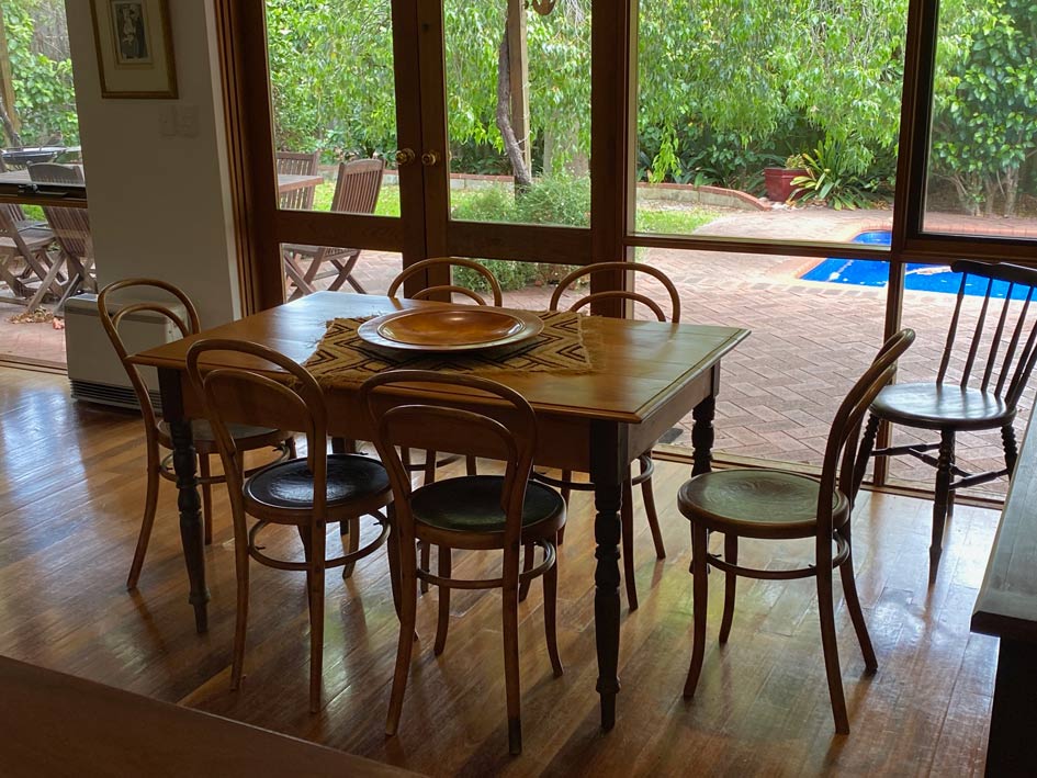
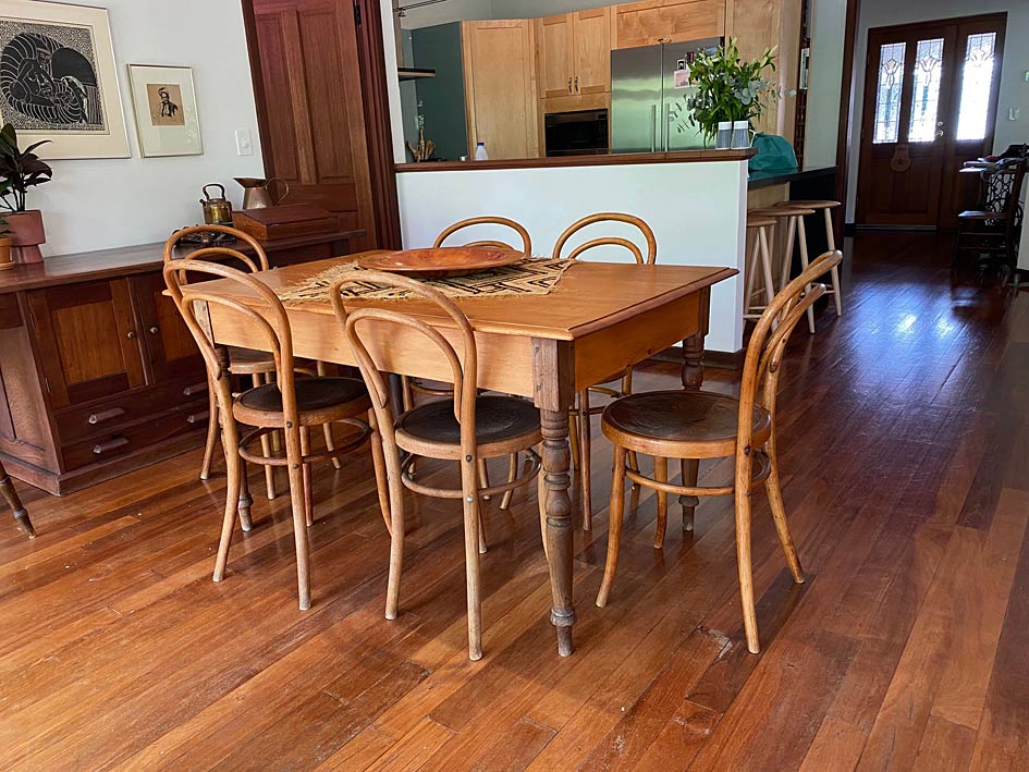
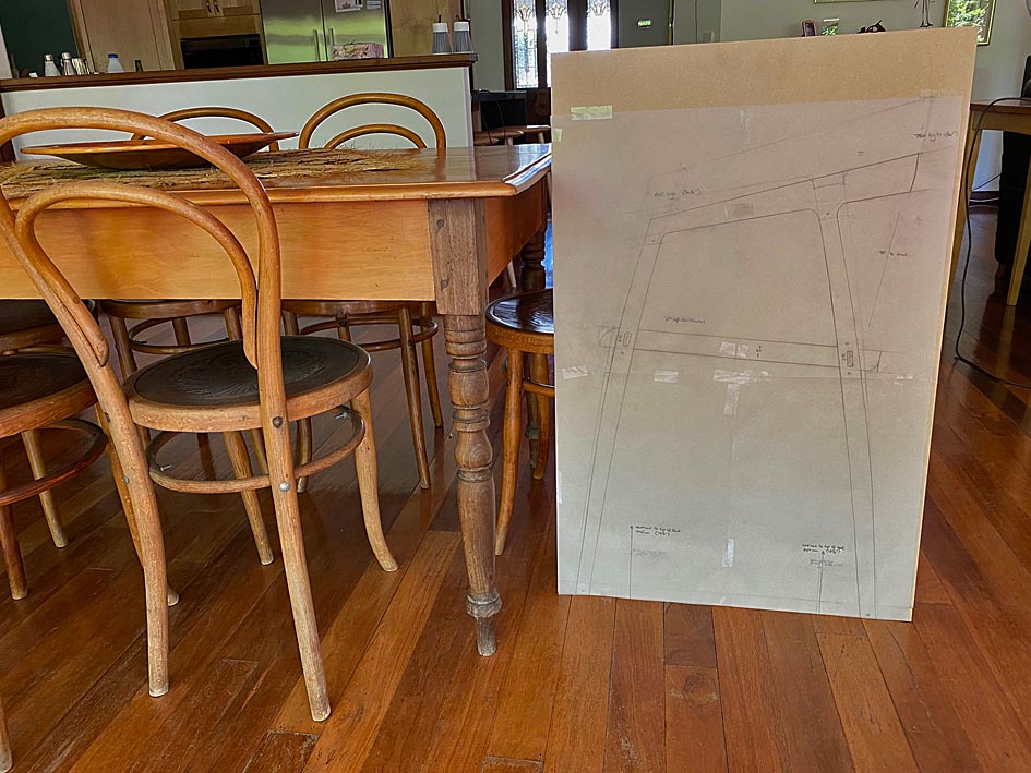
The design of the chair needs to compliment the bentwood chairs here, which are original early 1900s. The table is to be replaced with a longer, wider one.
This table is over 200 years old, and has great sentimental value. It is built of Yellow Wood (top) and Stinkwood (legs). We bought this after getting married. Now, 42 years later, Lynndy wants a larger table. The plan is a top in Rock Maple and round, parallel legs in Jarrah. Mid Century modern, and the aim is to blend two modern Mid Century carvers with the bentwood chairs. Consequently, a lighter look for the carvers is needed.
Regards from Perth
Derek
Added later 6 h 44 min 44 s:
Part 2
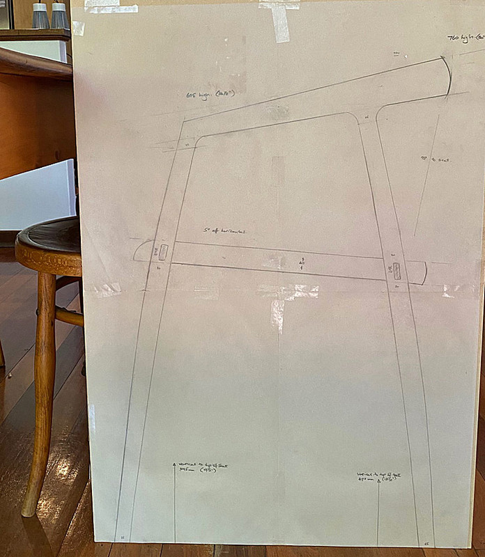
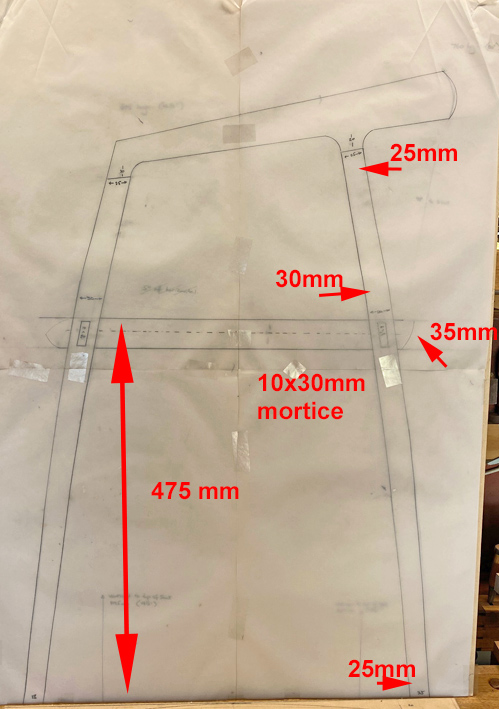
Here is the re-design.
The legs have been made thinner, with 25mm top and bottom, and 32mm around the seat area. The 35mm thick seat will be attached with mortice-and-tenons (not sure yet whether integral or loose tenons). These will be 25x10mm.
The curve has been retained in the legs ... since this is a desired feature to soften the look and also link with the bentwood chairs. The legs will now be round and not oval. The complication, in shaping, is that there is a taper and a curve.
The height of the top section has been reduced significantly. It is possible to see the original design below the new design ...
All-in-all much slimmed down.
Then there are finer details being worked out, such as the curve at the rear of the backrest and seat to link with the roundness of the bentwood chairs. The transition from the legs to the arm rest is borrowed from Hans Wegner ...
The plan shape for the arm- and back rest will come later.
The tilt is the same as other similar dining chairs. It is the same as the Wegner chairs I have. 5-9 degrees is the recommended tilt, and these are 5 degrees. It looks more here than it is probably because of the angle of the legs. I re-checked all a few times as this bothered me .. but it seems correct.
The plan has been to add a side-to-side curve/hollow to the seat, but not carve the seat deeper at the rear. If carving the seat deeper at the rear, it would be necessary to raise the seat (at the rear) by the same amount.
Regards from Perth
Derek
Added later 2 h 34 min 04 s:
Reflecting on the seat tilt ...
The front of the seat is 19 1/2" (at the top), and the rear is 18 1/2". The centre of the seat is the same height as the bentwood chairs. I had planned to have an even curve for the seat, but recognise that this will reduce its height. The rear M&T needs to be raised to accomodate for this.
Also, if I carve some of the rear of the seat that must also be accounted for.
I did test the height of the Wegner chairs I have - used as carvers when the table has an extension - and the seat height is actly the same as this plan. The legs of The Chair are vertical, and this creates a different appearance.
Anyway, I have 9 days to mull over this as we are off to Canberra to visit our son and family.
What will happen to the existing table? And since the height of the new chair arms will depend on the new table dimensions, will the new table have the same clearances for arms as the existing table? Do the arms need to fit under the rails, or just under the top? If under the rails, then either the new table rails or the new chair arms will need some adjustment.
Gary, the existing table will remain in the family. It will be taken over by our son. He wants 6 chairs to go with it!
The height of the table is pretty standard, and the new chairs have been re-drawn a few times to ensure that they fit. For example, as mentioned earlier, the centre of the new chairs is the same height as the bentwood chairs, and I played around with mock-ups of the arm rest to ensure this is at a comfortable height. Now playing around with the seat tilt, which will be made higher to take into account added carving out at the rear.
No particular critique from me Derek, but as usual you inspire me. I agree with the assessment of chair seat angle - it looks steep, but that is likely due to the relationship to the legs. 'Someday' I will tackle a chair project; if only we needed some to get me to 'someday'.
I particularly love this design challenge. I have just read here on WC Ian Kirby's comments regarding design competitions (probably as link in Ellis' earlier post), and your situation description is perfect for a design competition (in Kirby's view): it's not just 'Design a chair,' but instead is 'Here is the context of the other pieces and the room overall. Design a chair for this client.'
Henry, the "context" issue is always an important consideration. In my opinion, a piece must both stand alone and also co-exist with others. In the case of the carvers fitting in, they need to coexist with the bentwood chairs, and with the new-to-be-built table.
The round legs of the bentwood chairs, and their diameter, will be reflected in the carvers. The curves in the carvers will require a lot more work than straight, round legs (which could be turned), but are an important link to the bentwood curviness. I cannot get Beech to match the bentwood chairs (anyway they are old), but the Rock Maple chosen for the carvers will blend with the Rock Maple of the new table top.
Charles made a couple of important observations, one on another forum. These dealt with the armrest height and the seat tilt. I have copied the reply I made elsewhere:
(The armrest height forcing the chair further away from the table) is a important observation. You and my wife said (a while back) the same thing!
This prompted one of the re-designs. You can see an earlier design behind a more current design (but not the last design), where the height of the arm rest has been lowered ...
On its own this will not get one as close up as the bentwood chairs, however the new table will deal with this issue; The table will have 6" breadboard ends, and the aprons will be around 3" (as opposed to the 6-7" the current table has).
Incidentally, the tilt of the seat will alter. Your earlier comment made me aware that, while the tilt was the same in the drawing as an original Wegner The Chair (which I used as a reference), it did not take into account the seat shaping to come. Consequently, the front M&T will be raised 1/2" and the rear M&T by 1". That will give the external appearance of the seat being close to horizontal. The internal curve of the seat will drop the height 1/2" and then the internal scoop at the rear of the seat will be around another 1/2" deep (this will need to be calculated). I'll post fresh drawings when I return from Canberra.
Derek, I can't think of any good comfort enhancing reason for the seat to slope down towards the back. I'd say that almost one hundred percent of dining chairs I have come across in my life as either a user, or as dining/carver chairs I've made, or ones needing restoration or repair have had seats without a downwards slope to the rear. Level seats, I've found, are not uncomfortable. True, some have drop-in or stuff-over upholstery, some featured slightly dished plywood seating as in your Thonet style chairs, others with solid wood seats featured shaping for the bum, and there are those with cane or rattan bottoms, and so on. But, and I suppose I'm repeating myself, almost every single one of those chairs had seats that were basically parallel to the ground, e.g., level side, rear and front rails, or the underside of the solid wood seats of Windsor style chairs, et al, level with the ground, albeit the top face may have been bum shaped, or not.
Perhaps you're including the seat slope for aesthetic reasons or technical manufacturing reasons, but I don't think the slope you're incorporating is likely to enhance comfort, and I do rather wonder if the slope may somewhat detract from comfort, but to know that definitively I'd need to physically test a dining chair seat for myselfwith the slope you propose to know, which I've obviously not done. Slainte.
Since beginning this project I have become increasingly aware of dinning chair design, as if seeing them for the first time. I went out to dinner this evening at a restaurant and once again noted that seats are pretty much horizontal.
Regards from Perth
Derek
Added later 10 d 2 h 35 min 04 s:
Part 3
After some discussion, and a sudden increased awareness of dining room chairs, I decided to level the seat in profile ...
The seat will not end up horizontal, however, but be curved across the width, and further carved for extra depth at the butt end.
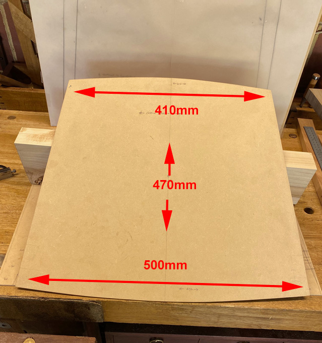
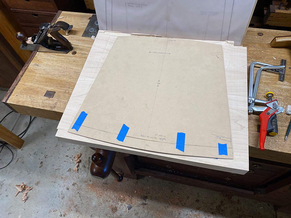
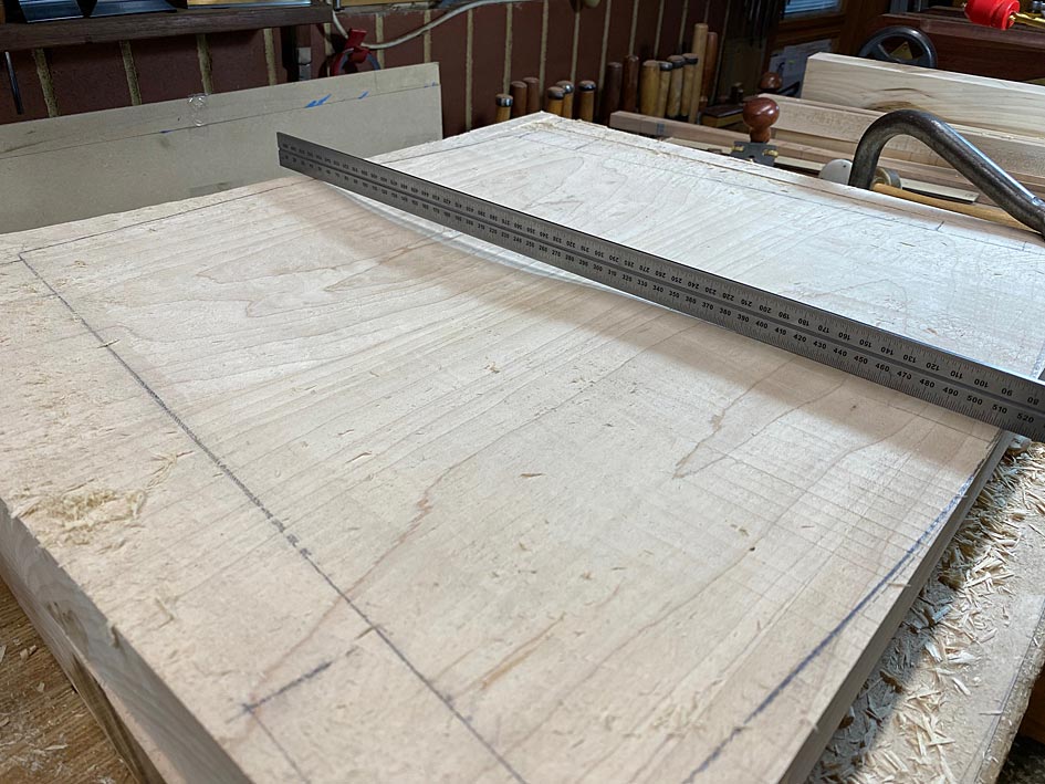
This is a basic template for the seat ...
The seat will be attached directly to the circular legs with through integral tenons for strength, and because the curved seat would make it difficult to use loose tenons. The tenon/mortice with be 10x30mm.
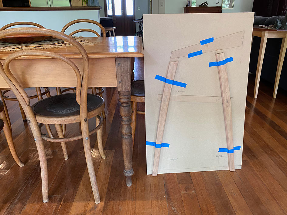
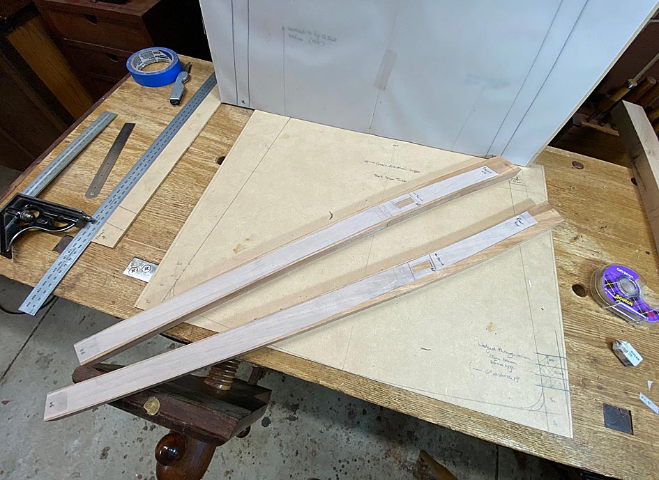
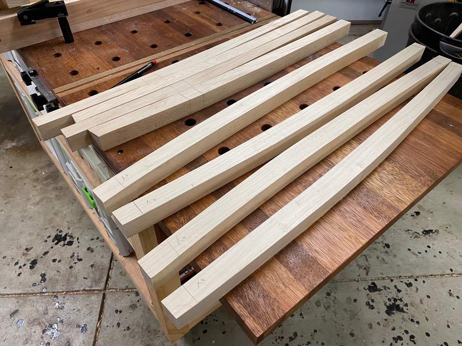
A tracing of the legs was used to create templates ...
In drawing the legs, each was mapped out separately, but with the same basic parameters: 25mm diameter at the top and bottom, and 30mm diameter through the centre. Similar curve plotted. The rear legs are roughly 30 mm longer than the front legs, and I anticipated that the proportions would differ as a result. However, when I placed the two templates on top of one another, they were exactly the same! And not only that, but the mortices were in exactly the same position as well!!
As a result, one template was used for both front and rear legs.
The plan was to bandsaw out each leg ...
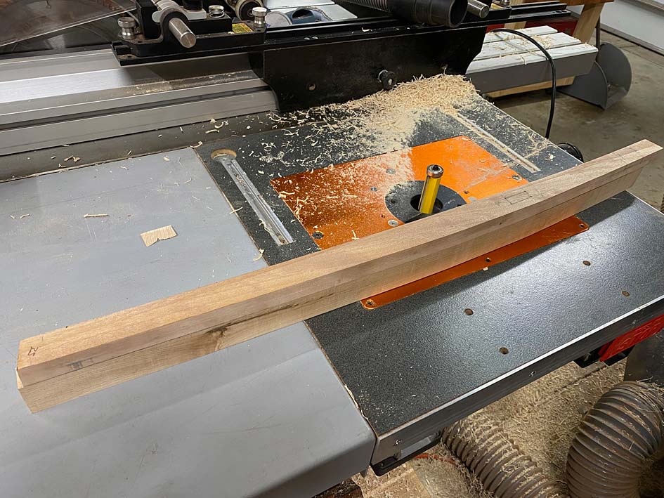
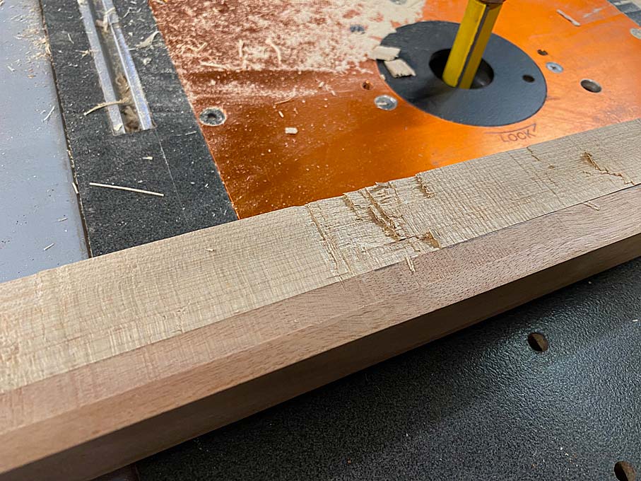
... and then use a pattern bit on the router table to trim the waste ...
This did not go to plan. The first leg was uneventful, but the second decided to explode. This is what I feared from the Rock Maple. Even with care in regard to grain direction, and resorting to climb cuts where needed, the router bit I had available was not helpful (the router bit I ordered had not arrived, and would be some days away).
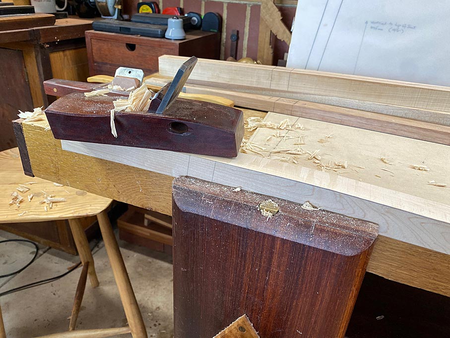
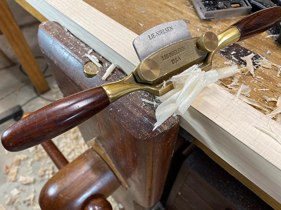
I had four leg blanks for the first chair cut out, and decided to do it in a method with which I am more comfortable ... with hand tools. Since there was so little waste to remove, a spokeshave on the inside curve was simple enough ...
... and a hand plane on the outside curve was even easier ...
It is vital to check frequently that everything is perfectly square. Morticing would not be possible otherwise.
Rock maple may be hard and brittle, but it cuts cleanly with a plane blade.
The leg blanks are 30mm thick. Once the outline is cut to match the template, the ends will need to be reduced to 25mm ...
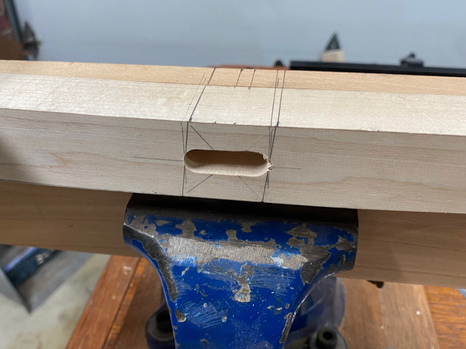
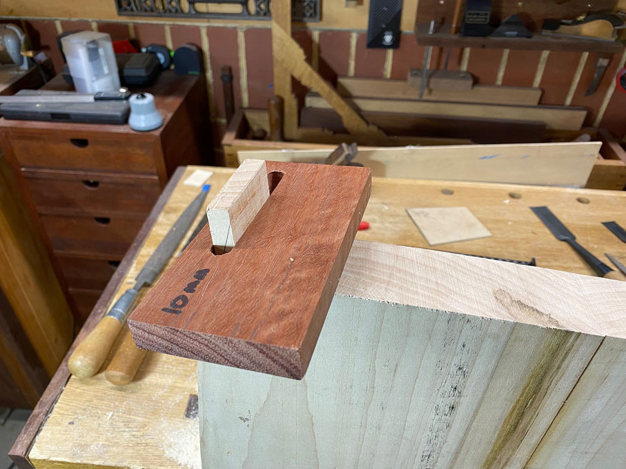
Lastly, for now, the position of the mortice was marked on both sides of each leg. The legs will be attached with through mortice-and-tenons, and each mortice is cut half-wway from each side ...
I am putting aside these legs for now, and will return to the final shaping, along with the other four, after the seats are made. which is next up.
Years ago (actually decades) I struggled getting through mortises even and clean on both sides. Then I was shown how, most likely here on WC. 1. Cut your mortise from 1 side to within about 1/4" (25+mm) of the other side. 2. Drill a 1/4" hole through the center. 3. Use a 1/4" pattern /trim bit in the router table to complete the cut from the opposite side. The bit, guided by the inside walls, will precisely match. 4. Bit will leave slight round inside corners to be removed with chisel.
Thanks Mark. My plan for the mortices is to use the Domino to excavate half-way from either side. This is why the guidelines are so important, and why keeping all square is necessary. I shall make a "holder" to ensure the Domino is positioned repeatedly. This is for later, but before the legs are shaped from square to round.
The question I have is whether to keep the ends of the mortices round, or square them off? Square ends make for easier square (hand cut) tenons .. integral to the seat), but round ends will look better - in keeping with the round legs.
Regards from Perth
Derek
Added later 1 d 16 h 02 min 31 s:
Part 4
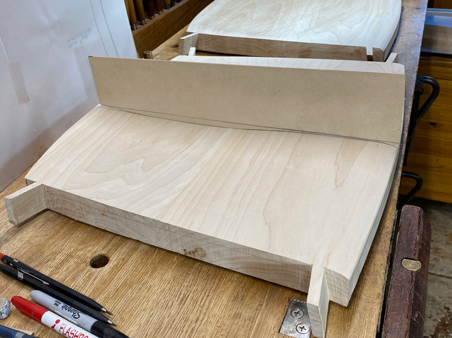
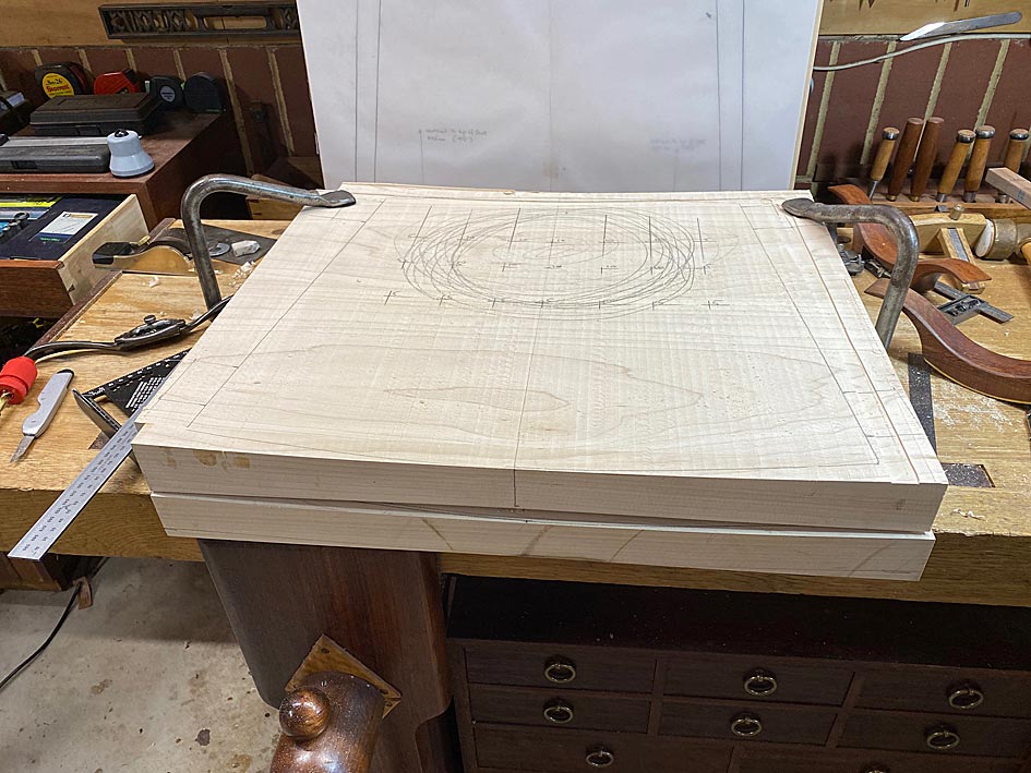
Shaping the legs have been set aside until the seats are carved. Shaping the seats is a challenge I have been looking forward to, but I must admit that two days have passed, and there is not much to show for a lot of effort. Let's have a look at the design of the seats.
The notable feature of these chairs is that they do not have a single straight line. Anywhere. There are three design aspects ...
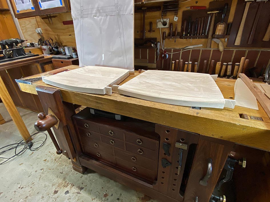
Firstly, the plan for the seats will be curved like these ...
However, they are to be 35mm high at the sides, and recessed like these ...
The underside must curve sympathetically with the seat ...
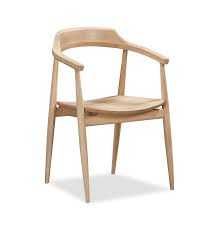
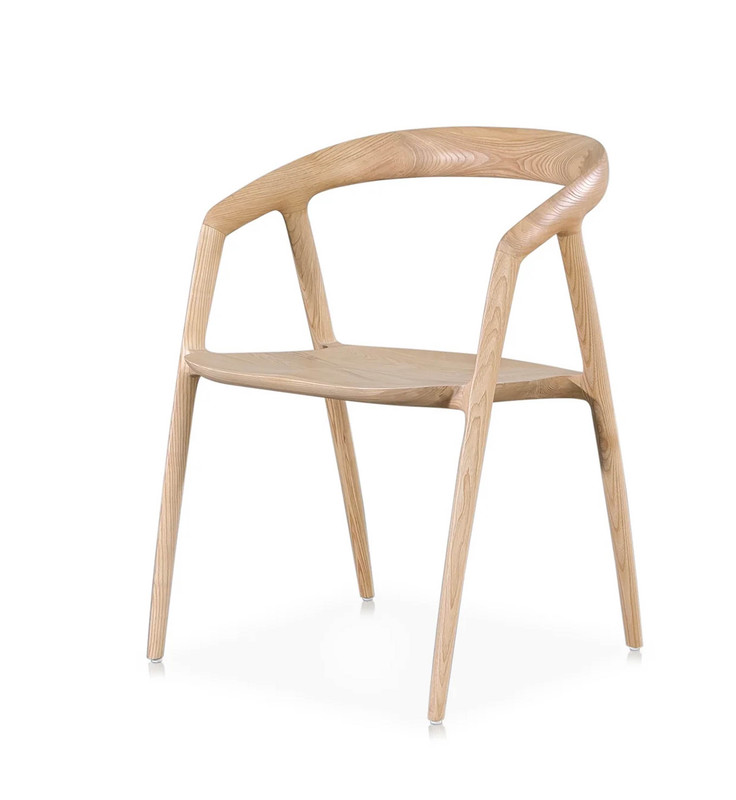
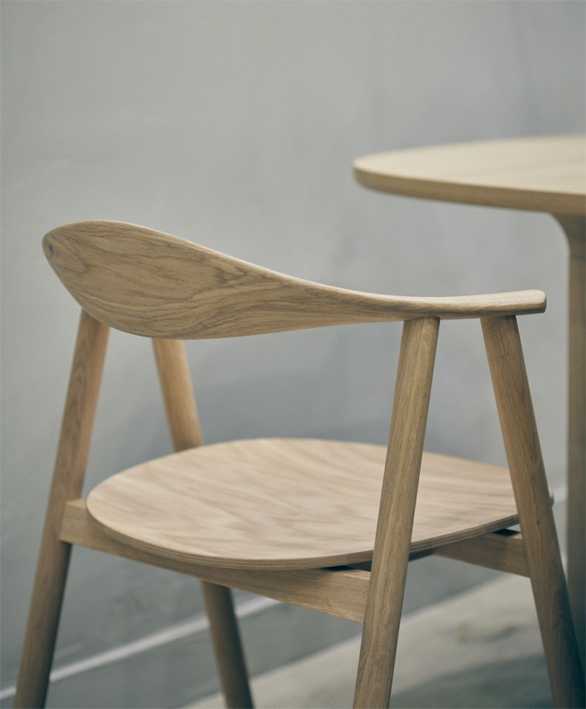
The third factor is that the seats will be attached to the legs with mortice-and-tenons, and will not rest on stretchers, as most chairs appear to do (and seen in an example, above). The reason for this is to increase the appearance of lightness. Shaping of the seat has to make provision for the integral tenons.
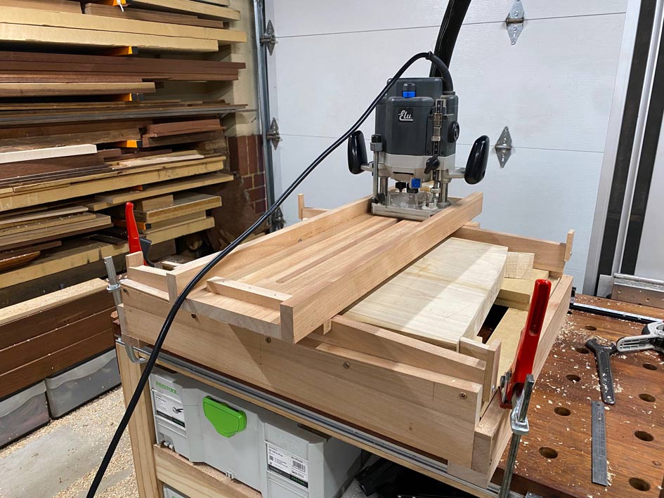
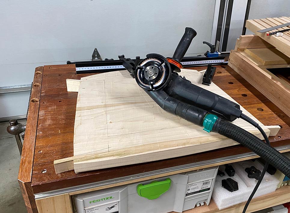
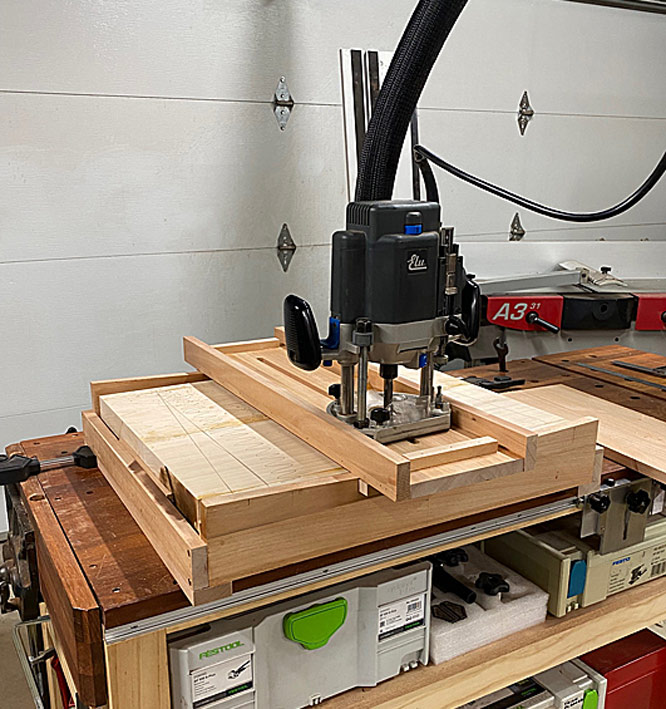
The seats are to be shaped with a combination of power- and hand tools. Power is needed .... this is Rock Maple!
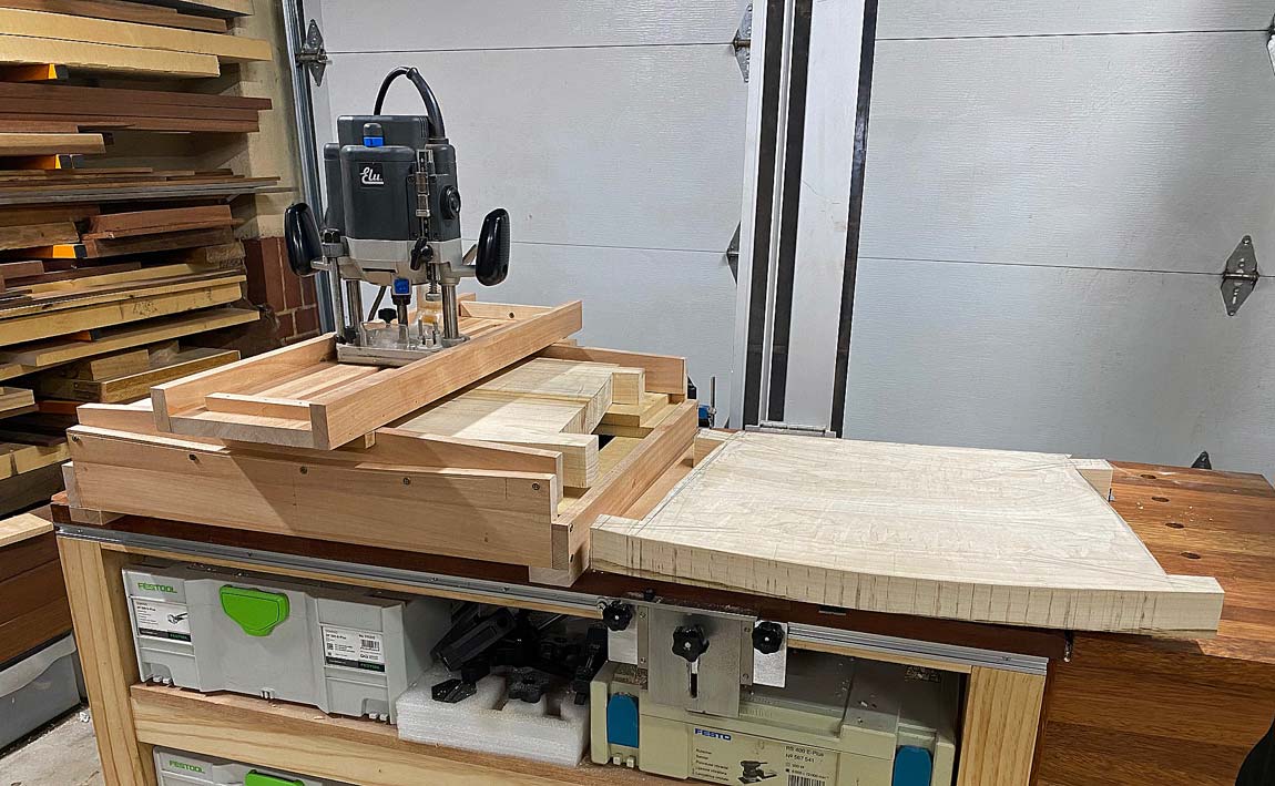
I spent time building a router sled to curve the tops and bottoms of the seats. The tops are documented here.
Today was 37 degrees Celsius (99 degrees Fahrenheit), and it was HOT in the unconditioned workshop, all windows and doors closed to be kind to neighbours. And it was slow going pushing the router back-and-forth. Plus it was messy ..
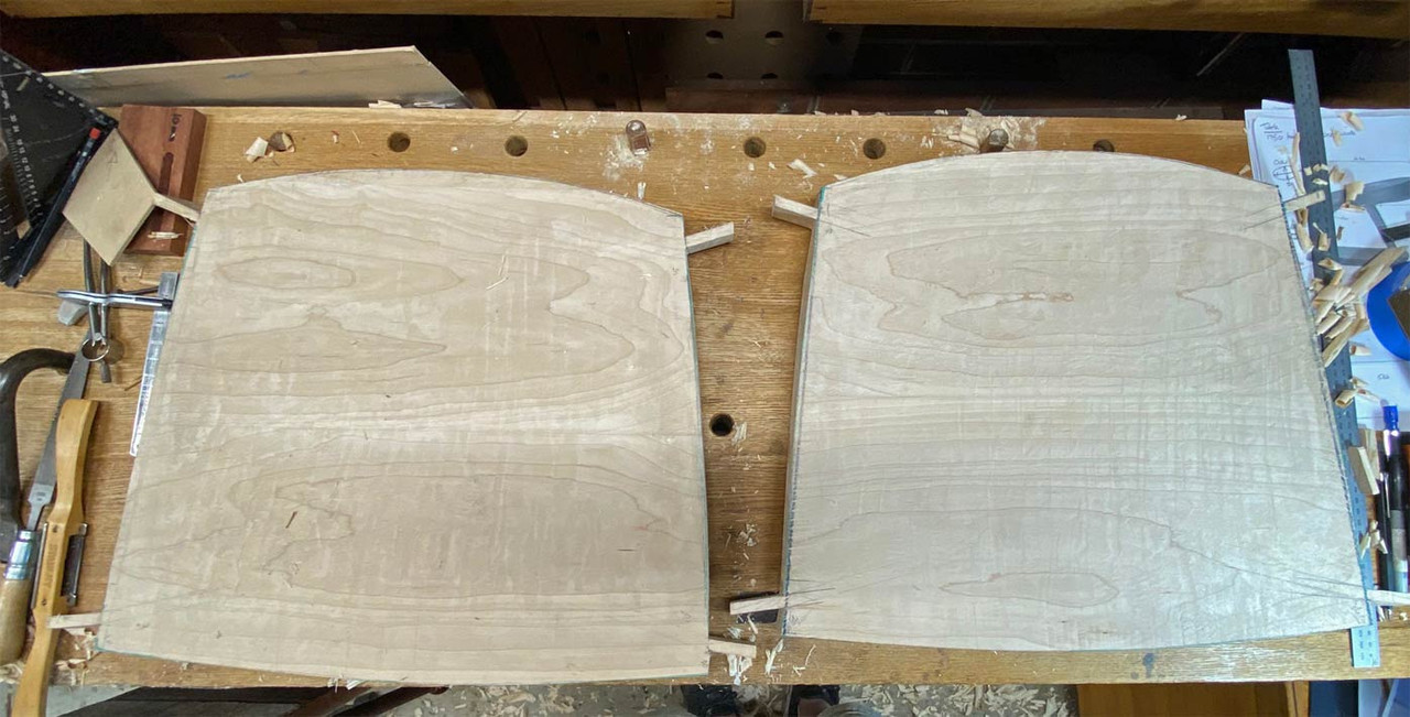
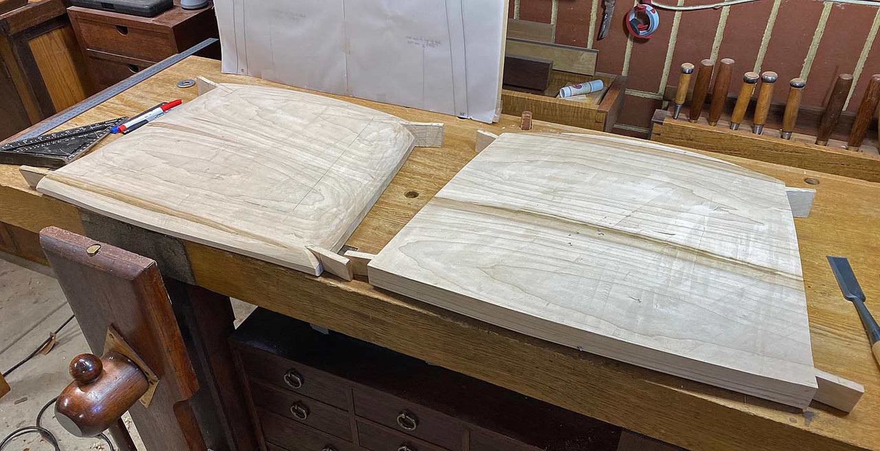
This was the result of my labours: two boards with the initial curves on their tops. These boards started out at 50mm thick.
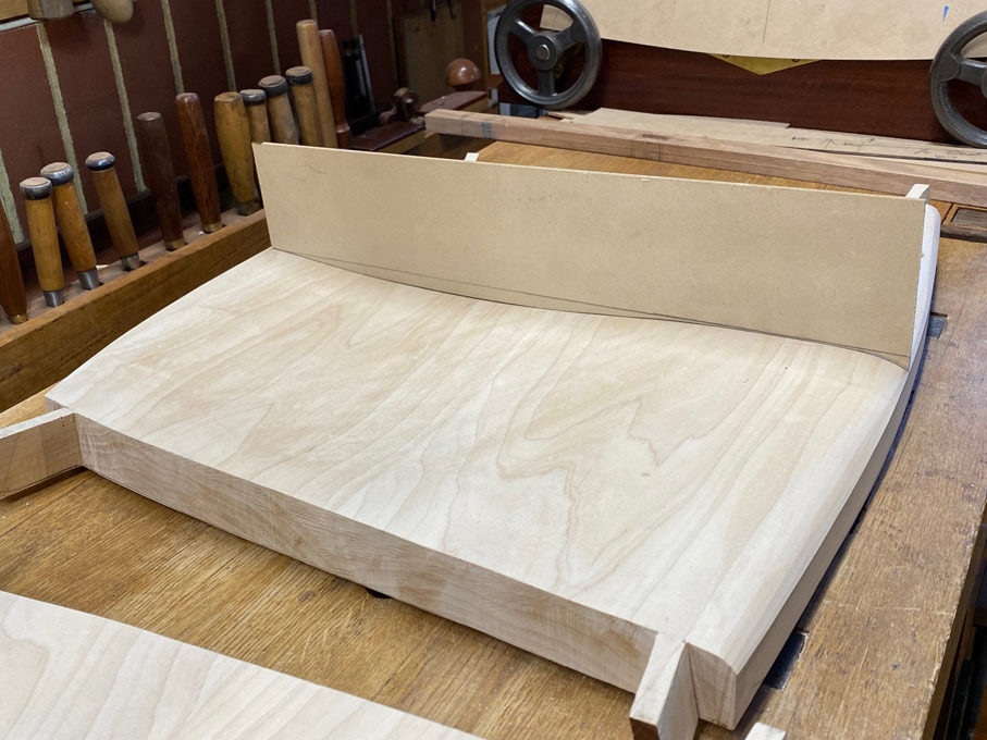
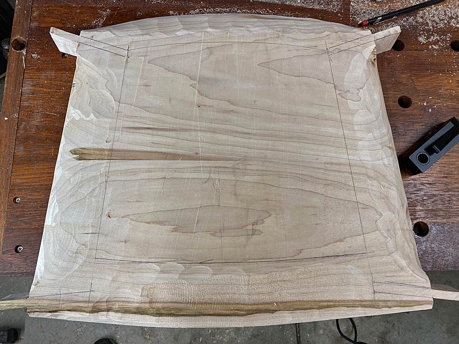
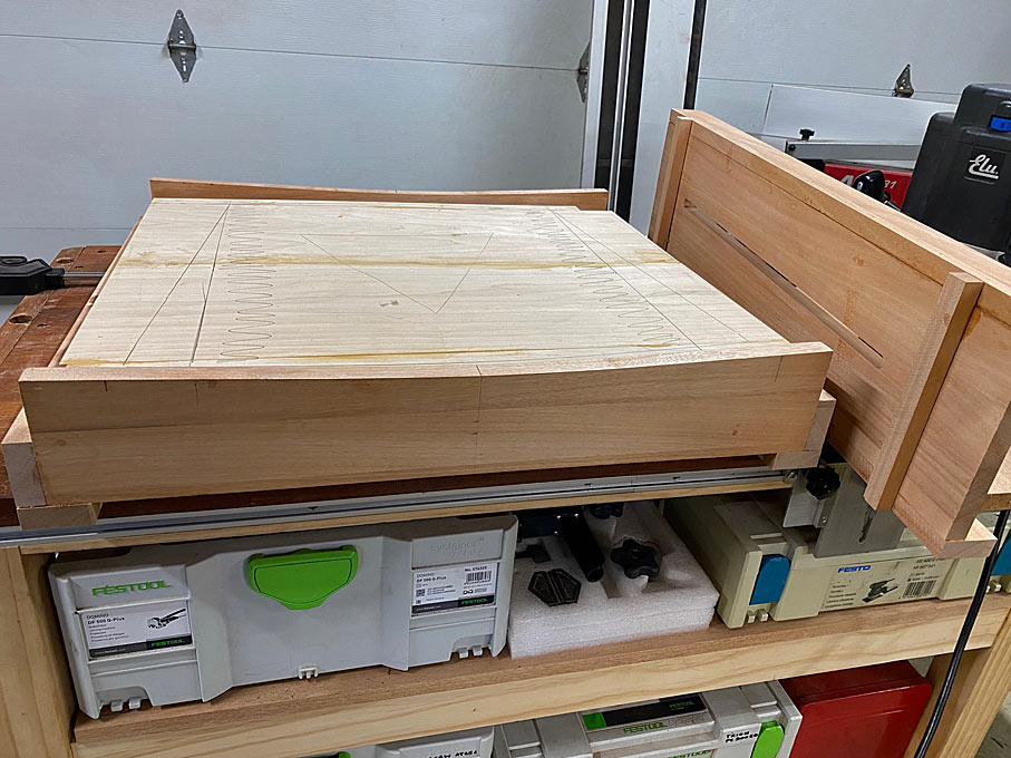
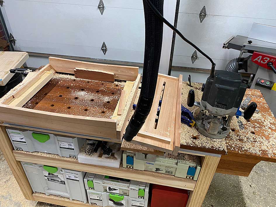
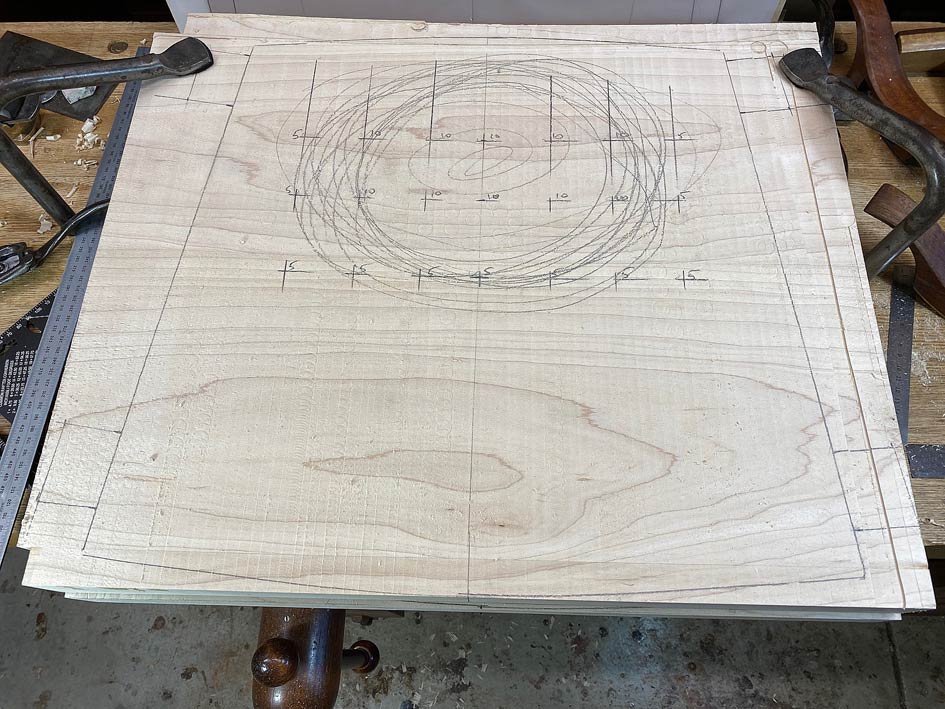
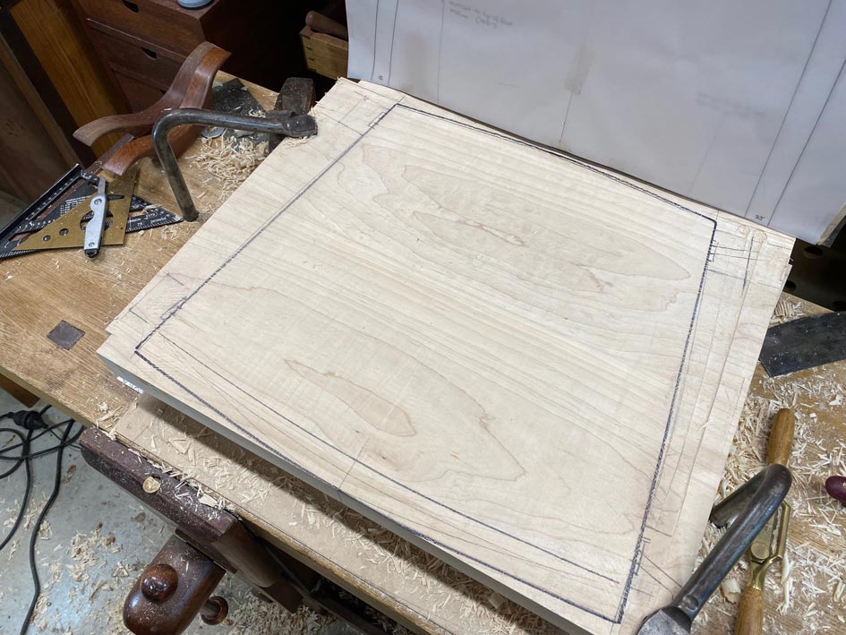
There is a template for the basic shape. This is simply to position the tenons. The outline will be modified later ..
The section for deeper hollowing is marked out, and a grid created to position 10mm holes through the centre and 5mm holes at the sides to guide waste removal ...
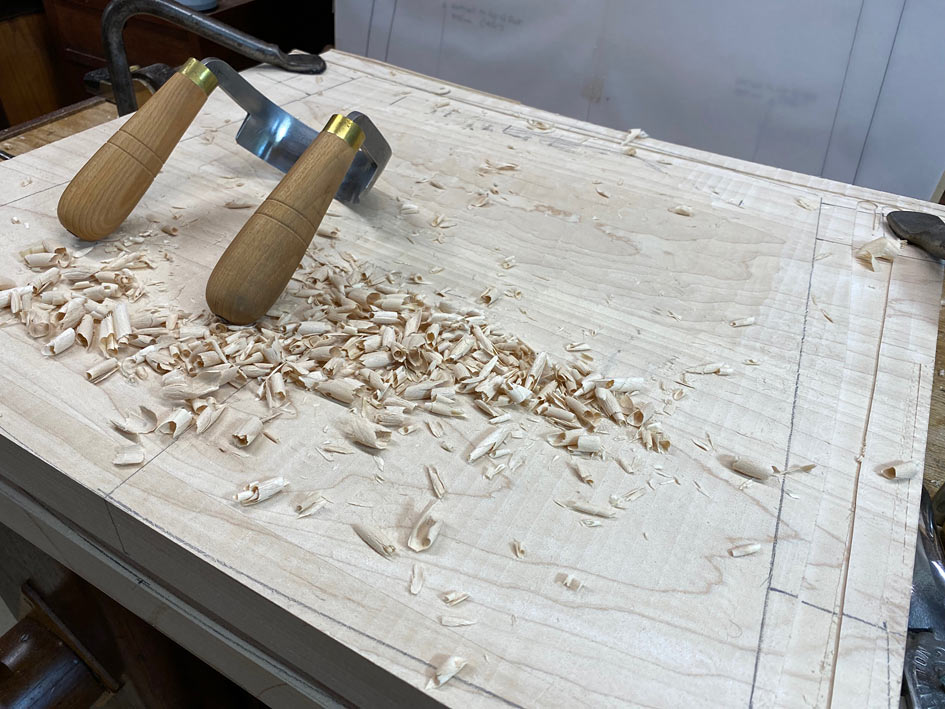
A scorp was used to remove the bulk of the waste ...
This was hard work - the Maple is hard stuff - and the next seat will use a different method. That will be revealed in the next post.
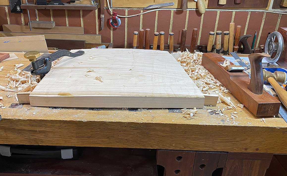
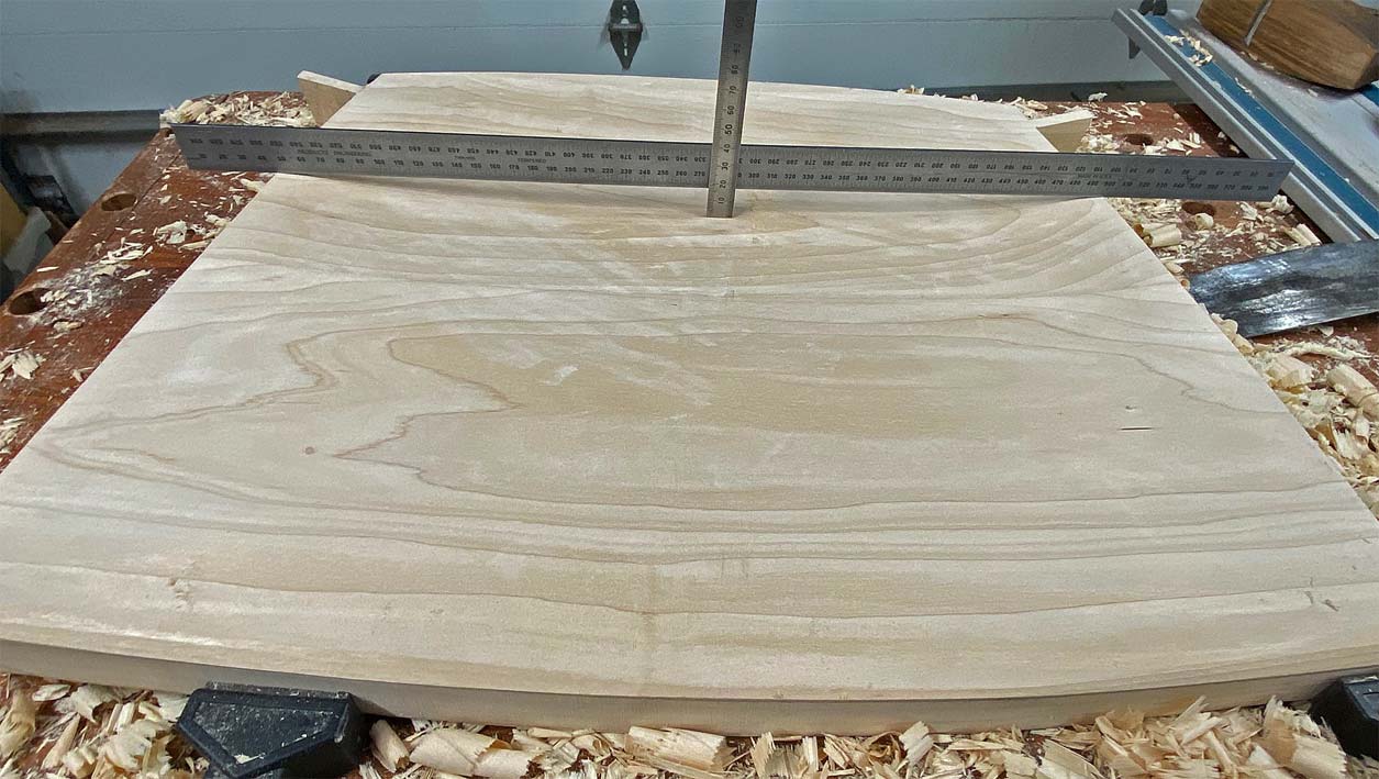
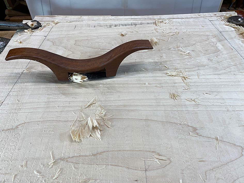
Shaping is done with travishers. I have two I built with different radius soles. This is one ..
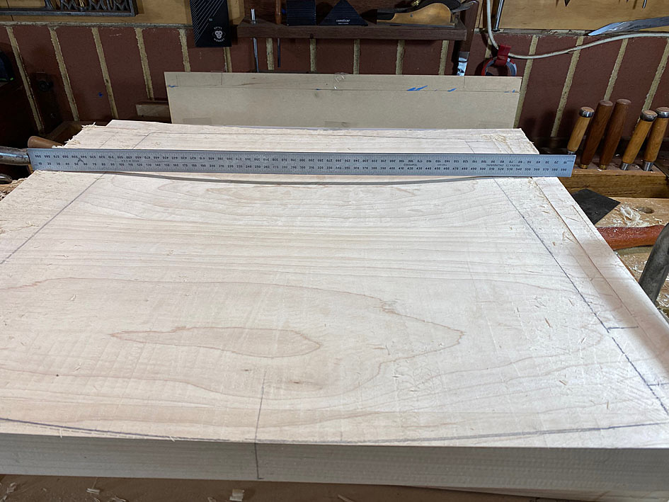
The result of my labours .... across the width ...
And through the centre ...
Lots of shaping still to be done at the front and underside.
In addition to the hollowing of the seat for comfort, the extra depth at the rear creates an effect tilt towards the rear legs. The amount of seat tilt can also be adjusted via shortening legs, if needed.
More soon.
Regards from Perth
Derek
Added later 23 h 51 min 58 s:
Part 5
The initial carving of the second seat ... time to learn something from the initial carving of the first seat! Rock Maple is bloody hard stuff. I have used a scorp to quickly carve Pine and Tasmanian Oak. I used a scorp to scoop out the first seat, and it was not fun in 37 degrees Celsius (98 Fahrenheit). Well today it is 39 degrees Celsius (102 Fahrenheit). Time to try something new.
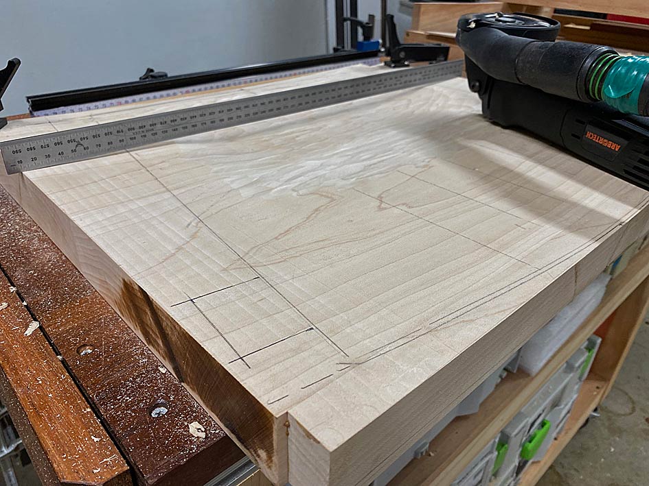
Here is the second seat, which has been curved on the router sled ...
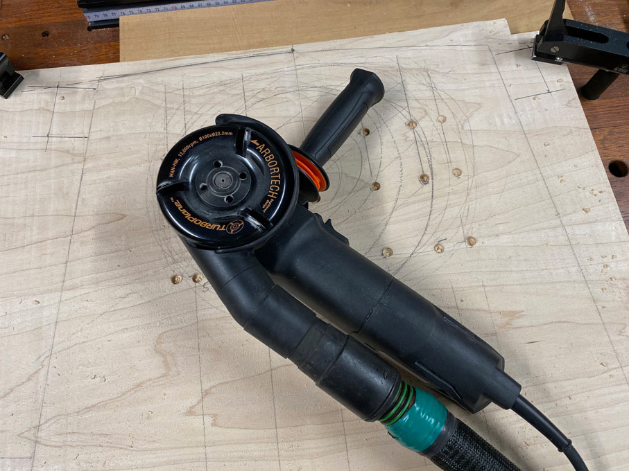
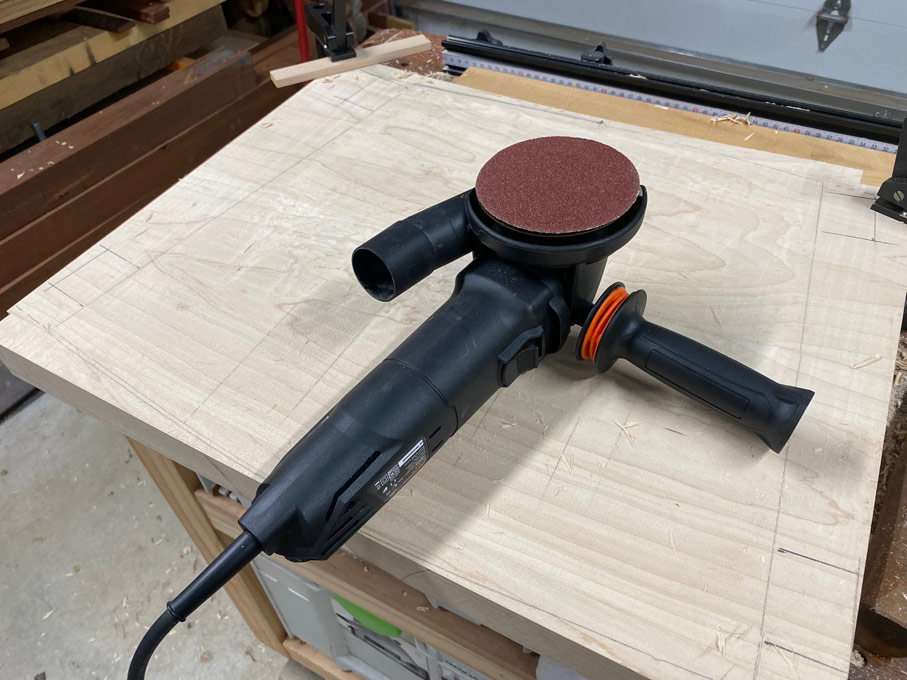
My 74th birthday present (3 days ago) was an Arbortech Turbo Plane kit ..
This can be set up in three ways: it can plane/joint rough boards, it can sand boards, and it can carve ...
It has variable speed, but I found carving is best at the fastest rate. Most importantly, it has some of the best dust control one can imagine. There is barely any chips to be found.
The Turboplane was impressively fast in taking the surface down to the drilled depths ..
It is an angle grinder, and noisy, but less so than a router.
I mentioned that is is a sander as well. I took the opportunity to try this out. 60-grit was rapid, and left a surface as smooth as a baby's bum.
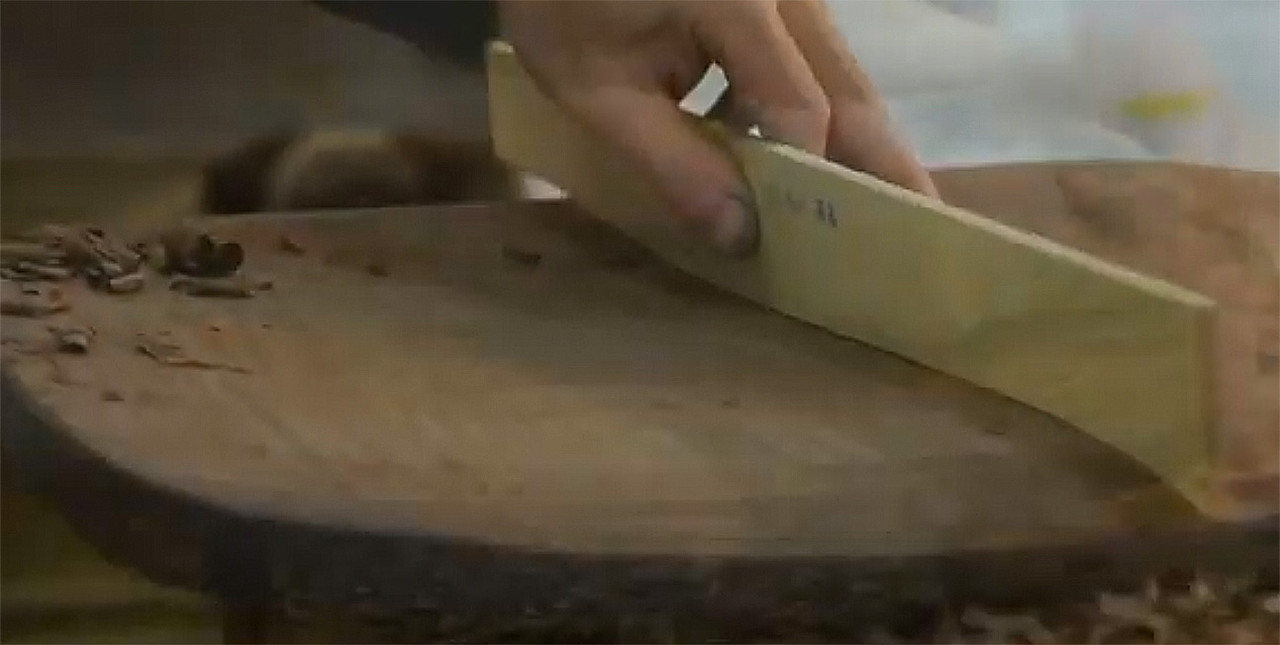
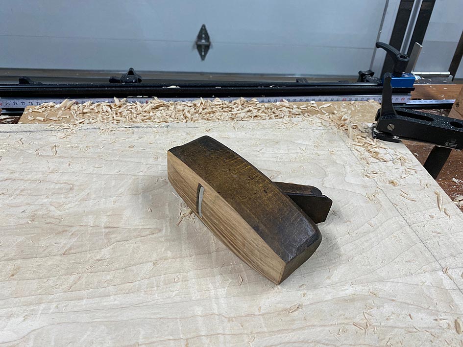
The second new tool used was one I made ... literally in about 10 minutes at this point in time. I had a small coffin smoother, about 4" long, with an open mouth and a single iron. It had been purchased in an "antique" shop for a few Dollars several years ago for the express purpose of turning it into a chairmaker's plane. I admit - I procrastinated ... until today. These are curved front-to-back and side-to-side. It was not much work, and this is what materialised ...
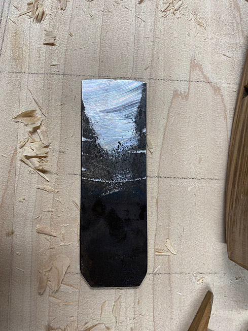
The iron was rusty, and simply flattened on the side of a 180 grit CBN wheel, and then shaped to match the curve of the plane. You can see that the camber is more like a jack plane than a scrub.
How did it work? Brilliantly! Really, after using the travishers, this plane left them in the dust ...
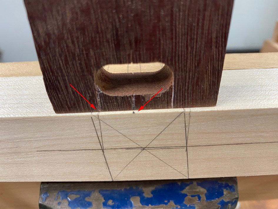
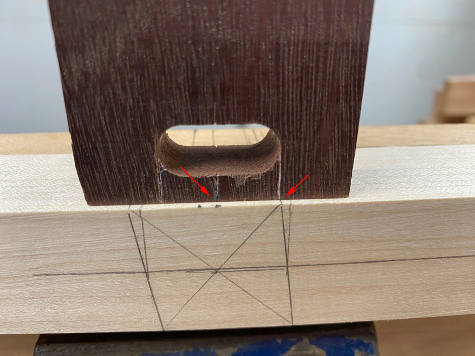
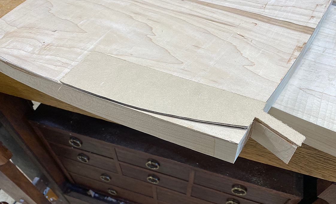
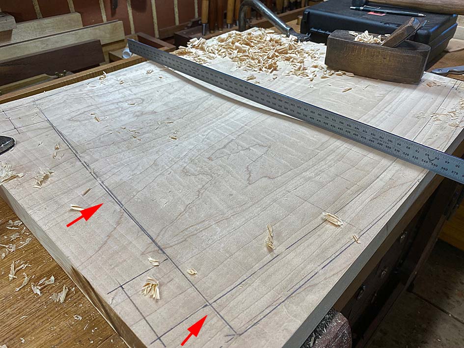
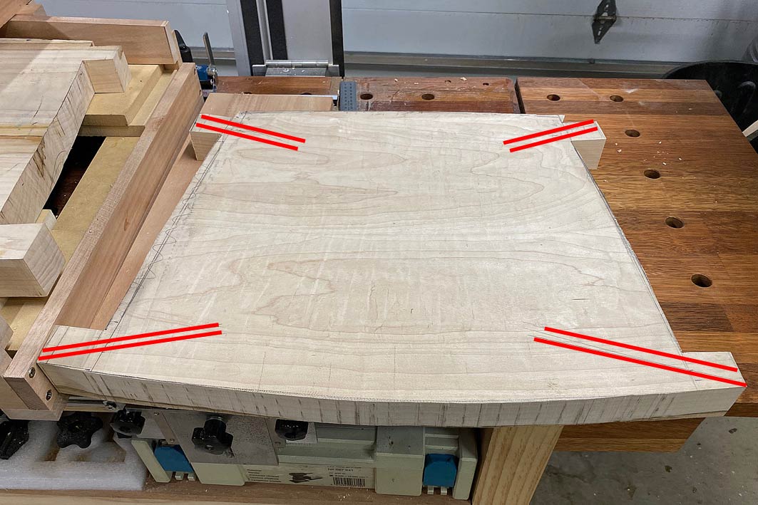
There are a couple of red arrows in this photo. The upper one points to the added curved side lines. The seats were temporarily made with straight sides, but they will have a slight curve (no straight lines on the chairs). The second red line points to where the front of the seat ends. It will be cut off at this line.
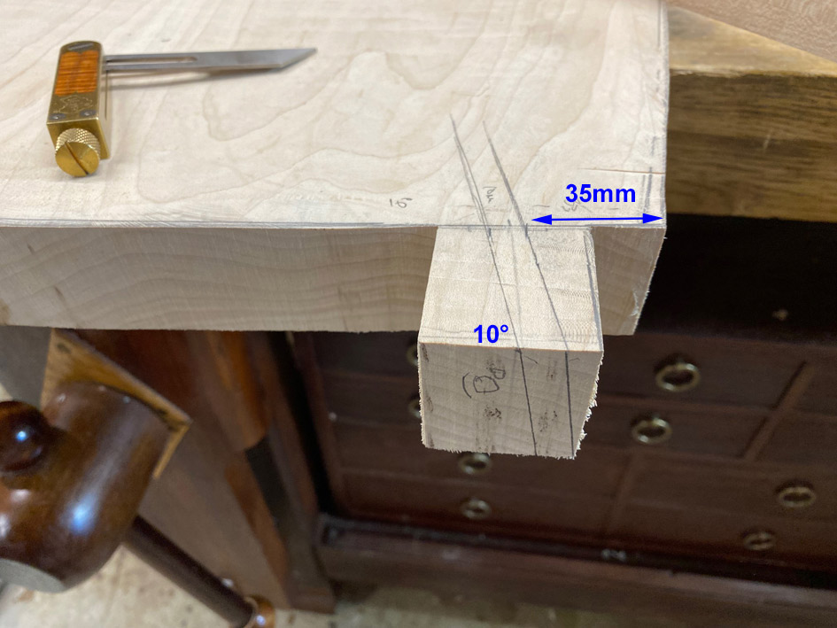
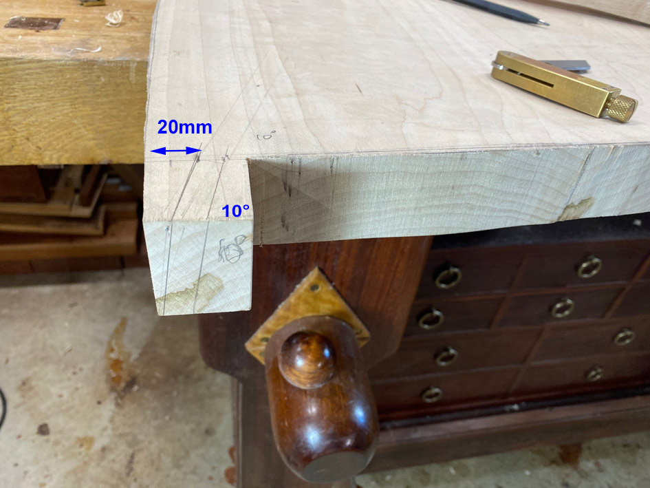
The photo below shows the outline of the seat prior to the underside being curved in the router sled. Note the sections left for the tenons, and the red lines here represent the angle these will be (20 degrees at the front and 10 degrees at the rear) ...
Finally, the router sled was converted from convex to concave ...
Very interesting on the shaping of the second seat. On the coffin plane, you put a curve front to back and side to side, correct? Was it by eye or did you have a reference as a starting point for reshaping the plane?
Did you have any safety concerns about the Arbortech? On a blog that I read, the author raised some safety concerns about using either an Arbortech or something similar and advocated for a scorp. With the hardwood that you are using, power makes a lot of sense.
The coffin plane was shaped by eye. However, it really is not complicated as the aim is to make a fine curve first side-to-side, and then back-to-front. The sides-to-side I used a hand plane, and the back-to-front I use a stationary belt sander. Very carefully!
The blade was inserted into the body, and the curve marked. Then taken to the bench grinder to shape. It worked first time. Very pleased.
The Arbortech I found works more smoothly at full speed. It took me about 1 minute to get used to it - primarily, it wants to pull the blade in the direction of rotation. A light hand and anticipation counter this. Then it is very controllable. Plus different angles cut more or less. Lastly, the dust control is remarkable, absolutely amazingly good. This was the reason I was prepared to get one.
There is also a surfacing fixture which acts like a power planer.
And it is designed and manufactured in Western Australia!
Regards from Perth
Derek
Added later 04 min 04 s:
Part 6
Andy, on the WoodHaven forum, left a message which was remarkably predictive of what I had planned to write.
For me, the interest is in the problem solving. To make a single chair, with all parts curved, would be a challenge. But to make a matching set, you are going to need a tight system of reference edges and surfaces, to be removed only when all shaping is complete. Your methods so far make sense - of course they do! - I just mean that it sometimes takes me a minute to catch up and see why you are making a part the way you are. I'll be happily admiring the rest of the build.
Andy, spot on! In fact, you preempted the very topic I planned to write.
Everything in furniture building requires forward planning. This is even more the case where, as here, these chairs have not been built before, do not come with plans, and are based on sketches I have made. One sees chair builds on YouTube where the Maker lays out a template, cuts it out, finishes it with a template router, and then starts glueing parts together. If only ...
When one looks at the chair design, attention is taken by the arms and back. Yet these are aspects which will be approached last. Far more important is the seat, since this creates the plan for the arms. But, building a seat like the one envisioned is complex as it has two shaped sides, a top side and a bottom. Most seats are carved only on the top, with the underside being left flat.
In addition, I have seen very few seats which are attached directly to the legs. Almost all rest on stretchers, with the stretchers morticed to the legs (e.g. The Chair). The latter is easier to construct as you build two sides, and then link them. With integrated tenons in the seat, one has to make allowance for the tenons, and these need to be cut at the correct angle before the underside of the seat can be shaped. The reason for this is that we need a flat reference edge to mark the tenon angles (which come from the drawing).
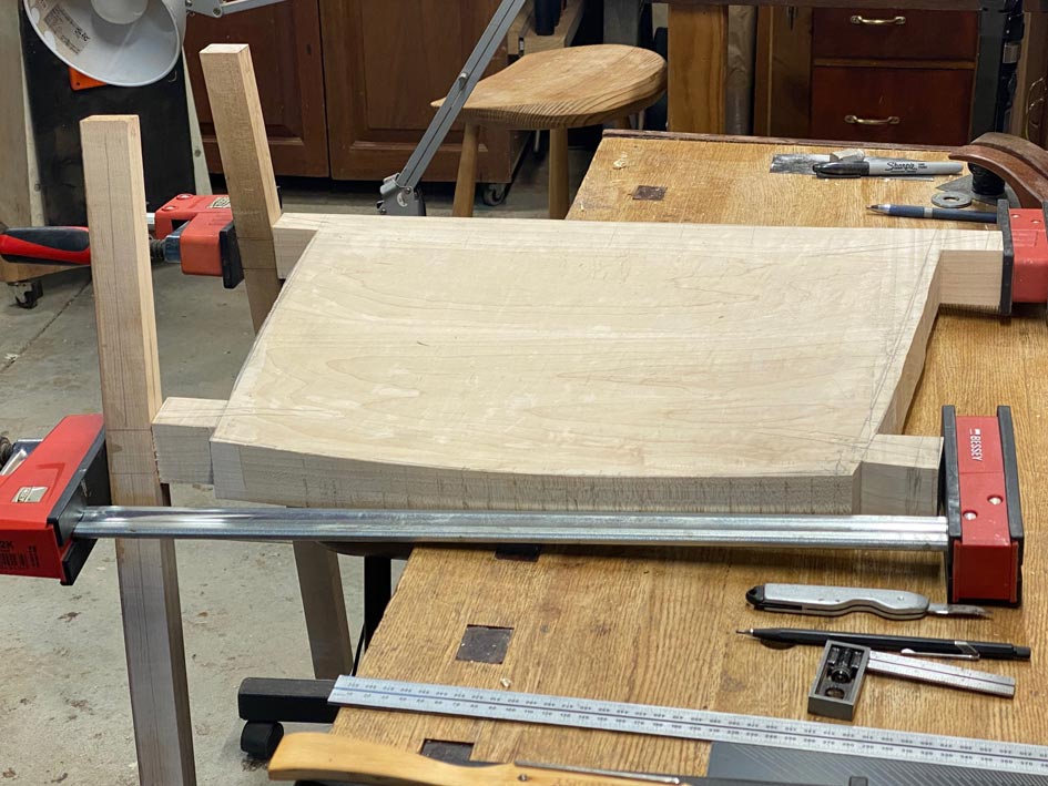
Here is the seat at the end of the last post ...
The underside is flat at this stage (being the reference sides), as are the sections where the tenons will project. But ...
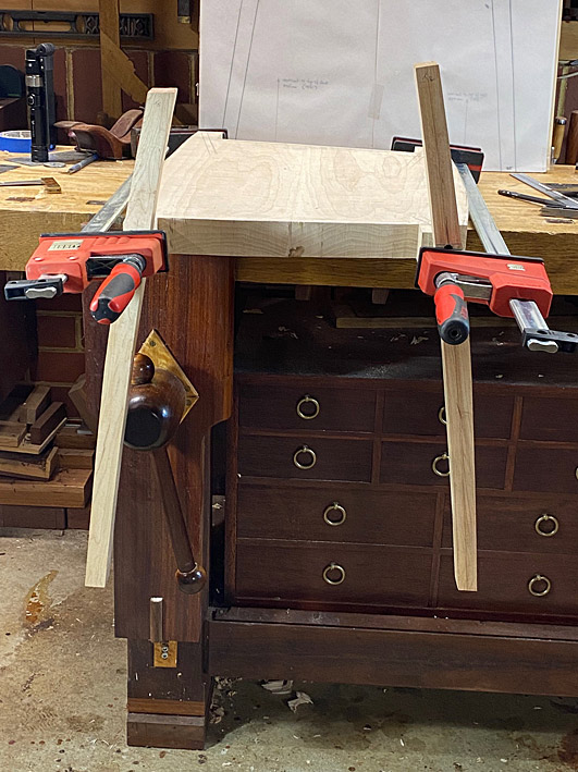
While I am confident about the angle of the tenons, I want to be sure of this, and this requires that the legs be clamped to the ends of the seat at the angle predicted. The legs have been left flat - not yet rounded - as it is easier to add a mortice at this time.
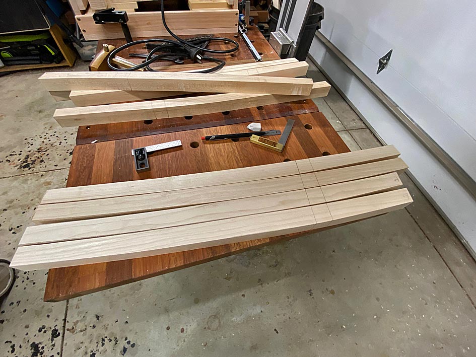
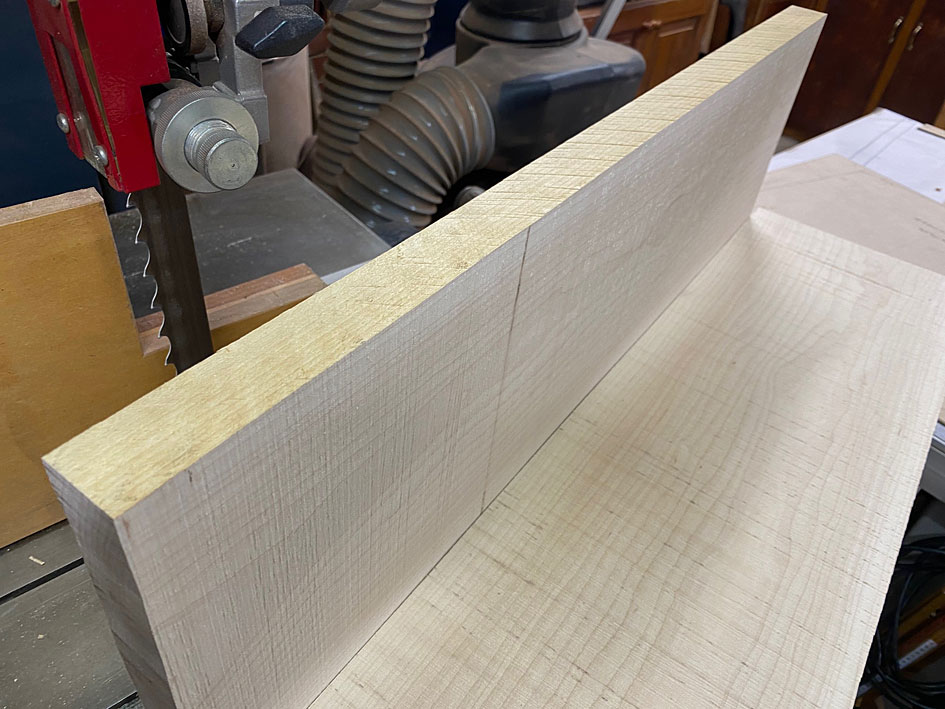
So the next stage is to do just this, but I only have legs for one chair. As a result, work stopped to complete the other four legs. First, a section was cut off one of the 3m long (x 250mm wide x 50mm thick) Rock Maple boards (my wife helped me load this!).
Easier to crosscut on a MFT with a tracksaw than a tablesaw. Mine is a 20 year old Festool I purchased about a year ago in as-new condition.
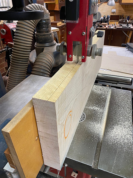
The section was re-sawn to 32mm and then planed to 30mm. Great tracking by the combination of a Hammer N4400 (which I have had for about 15 years) and a 1" Lenox Woodmaster CT blade ...
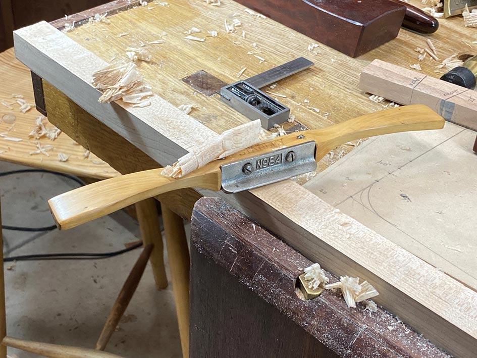
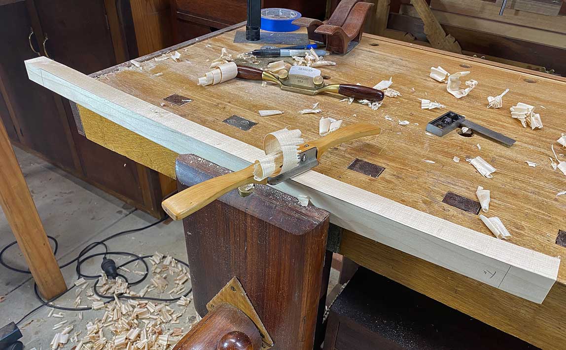
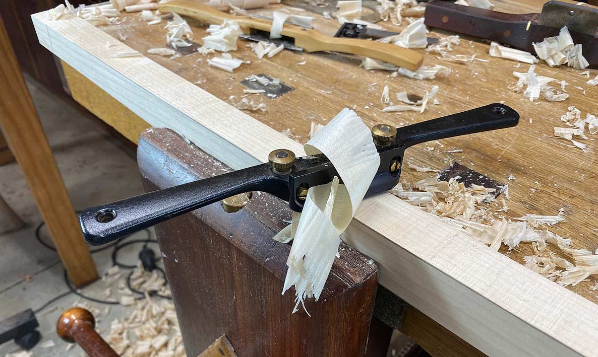
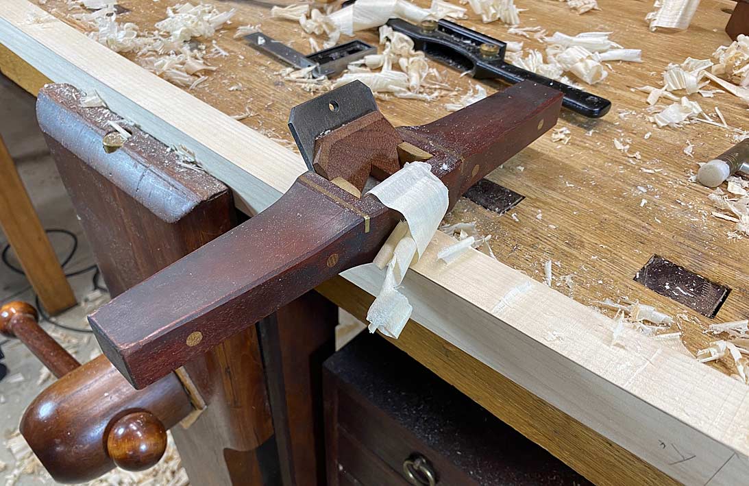
As I mentioned in an earlier post, it is less stressful to mark the legs with a template, bandsaw to the lines, and then use spokeshaves to clean up. Here are some of the spokeshaves I use ...
A Stanley #84 boxwood spokeshave excels in taking thick shavings. This is where I begin ...
Veritas make a copy of this in the form of their LA Spokeshave, and it is very good (I use one or the other, not both) ...
Many years ago I was gifted a flat and round spokeshave by Terry Gordon (HNT Gordon tools). It is a Malaysian/Asian design with a high cutting angle. This is my go-to if there is any reversing grain ...
Lastly, the LN Boggs spokeshave takes very fine shavings and is used like a smoother to finish the surface ...
I'm also really enjoying this build. I hope more members will let us follow along with their work. Especially with chairs. I see folks who make chairs as I do musicians. I admire them but have yet to imitate them.
A few years ago I thought I would make a set of four chairs for our dining table. I got as far as cutting out blanks for the first one. The next few steps did not go well. I stashed the parts in the attic for another day. I'm still traumatized by the experience.
Especially after today, this build really feels like a step forward, a step sideways, and then a step forward again ... cha cha cha ..
I really do know where I am going, and what has to be done, even if it does not seem that way! Templates would have made the process easier.
So where are we up to? Well, it is the stage where the through mortices are made. We start with 8 legs ..
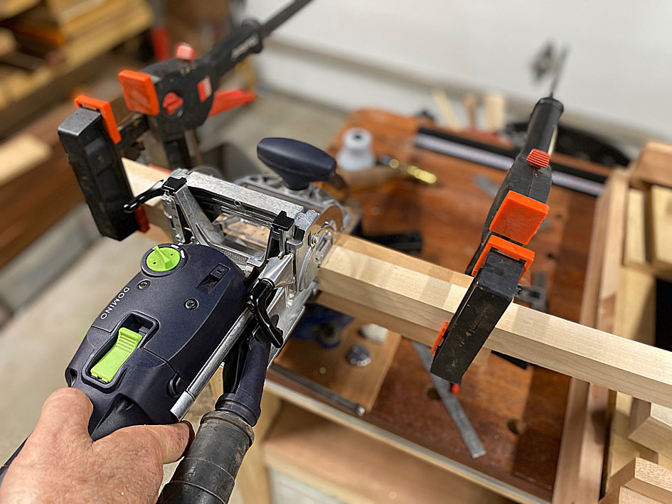
The mortices will be made with a Domino ...
Then it gets a little complicated :
1. The legs are curved. 2. The mortices are cut half way from each side, and must be aligned well to meet in the centre. 3. The Domino can cut a maximum of 24mm width. The mortices are 30mm wide (by 10mm).
I have a guide for setting up the Domino to cut a specific size mortice width. This is for a 10mm x 24mm domino. Since the legs curve, the boundary lines for the mortice angle. The boundary lines cannot be dropped down on the vertical, so ...
First set the left side centre indicator ..
.. and then the right side indicator ...
Two plunges of the Domino creates this ..
Repeat on the other side.
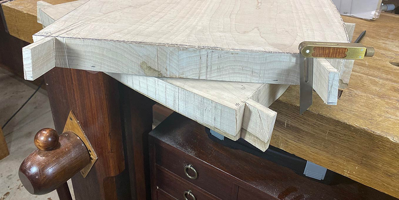
With all 8 legs morticed, I began to lay out the tenons.
All the legs are angled at 10 degrees towards the centre. This is prior to cutting the tenons ..
Rear leg ...
Front leg ...
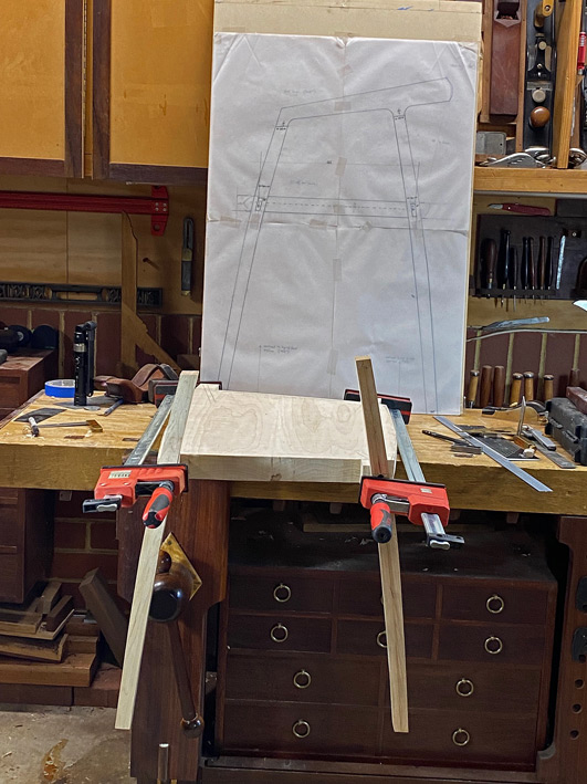
Here is the mock up with the plan/drawing in the background ...
And a close up ..
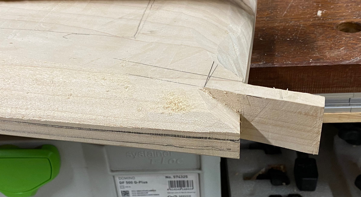
A last photo for today - taken from the rear. The ears represent the stock for the tenons ...
Tomorrow the tenons will be cut, and then we can get back to shaping the seats.
I have gone back-and-forth on doing it this way. I can understand why so many builds use loose tenon joinery. Simply, it is easier to do so than creating integral tenons. It also makes it possible to shape the seat fully separately, especially the perimeter. The seats here have been roughly cut to shape, and only the top partially sculpted. It has been a very round-about way of building ... more steps that could have been avoided.
So why build this way? Well, I want integral tenons as they will be stronger than loose tenons. It is also difficult to rout the mortices in the edge of the seat owing to the awkward angles involved. Lastly, adding mortices may not be possible owing to the reduced depth of the sculpting.
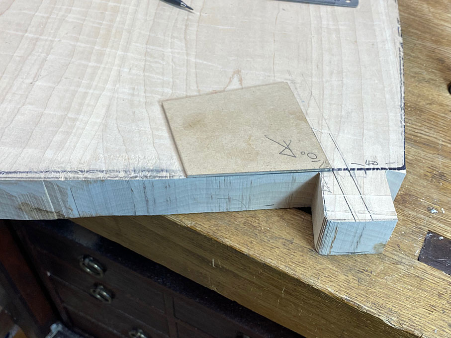
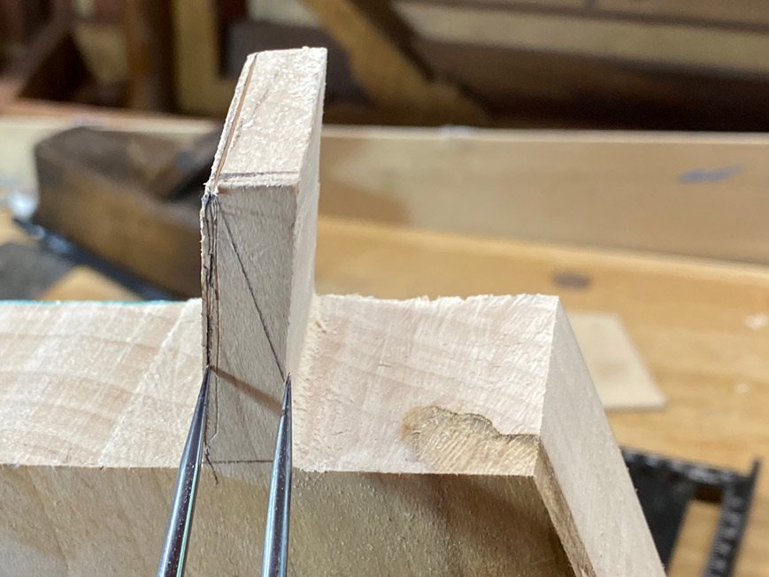
The tenons are not straight-forward as they angle inward at 10 degrees, creating compound angles, as will be seen shortly ...
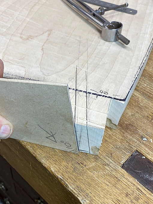
Using a template for 10 degrees, the angles for the tenons were plotted on the ears ..
Dividers are used to mark the 10mm width ..
There is also a 10 degree splay angle to add ...
At this stage my spatial-ability challenge came to the fore and I was in over-load with angles. Marking out the angles on the reverse side gave me the biggest headache, and I came so close to accepting loose tenon joinery!
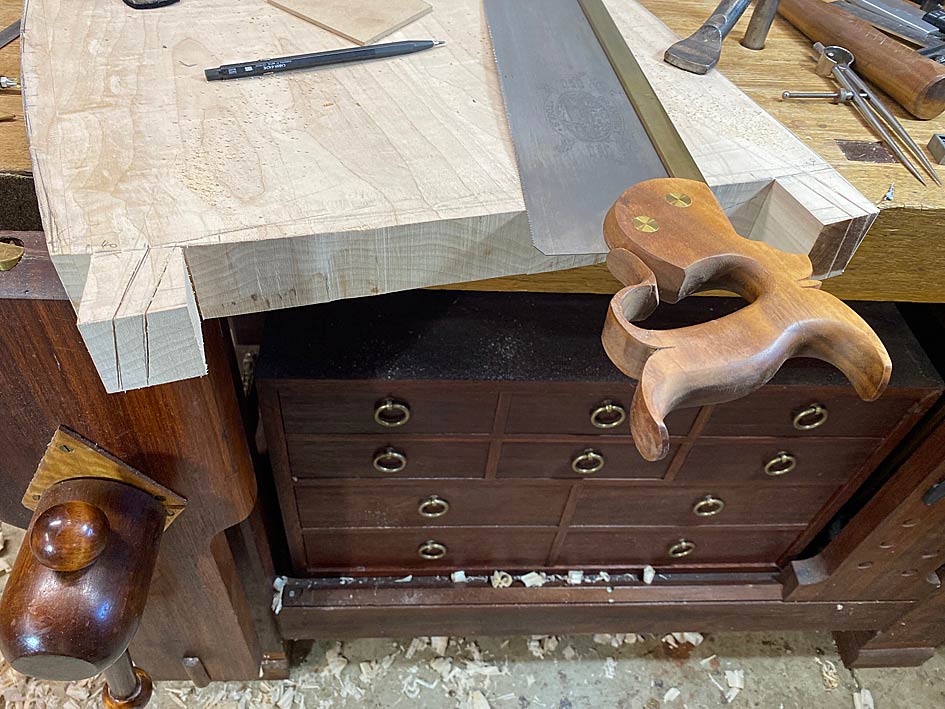
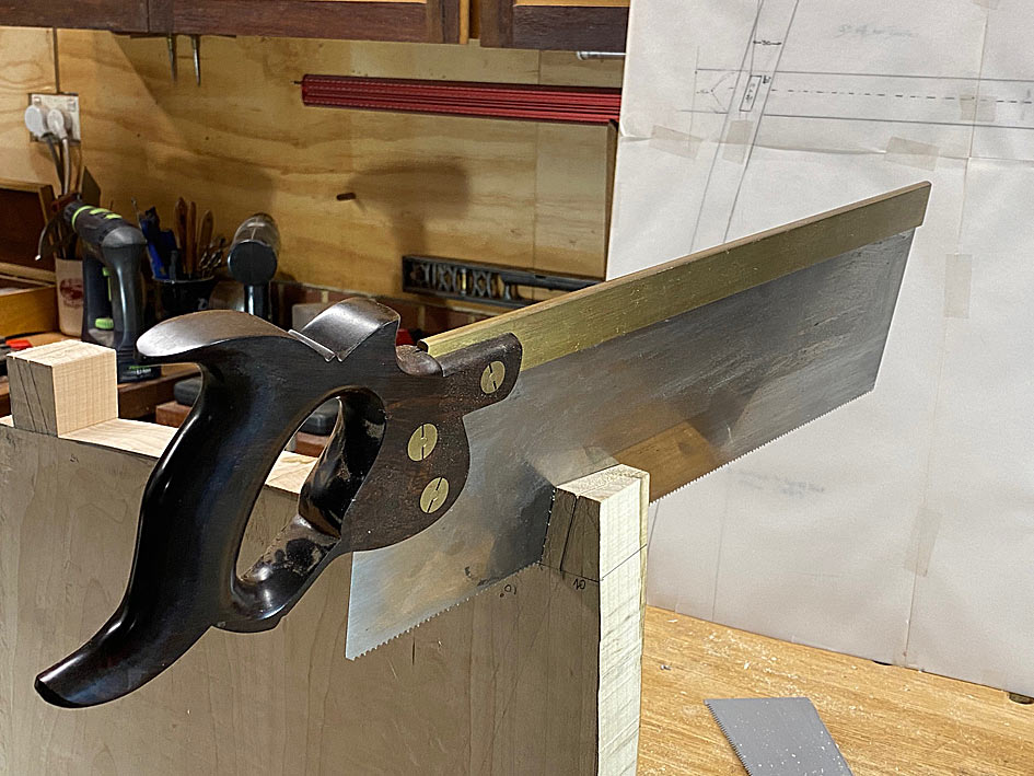
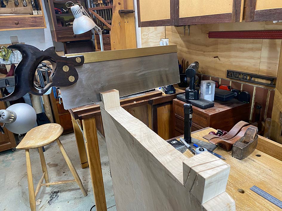
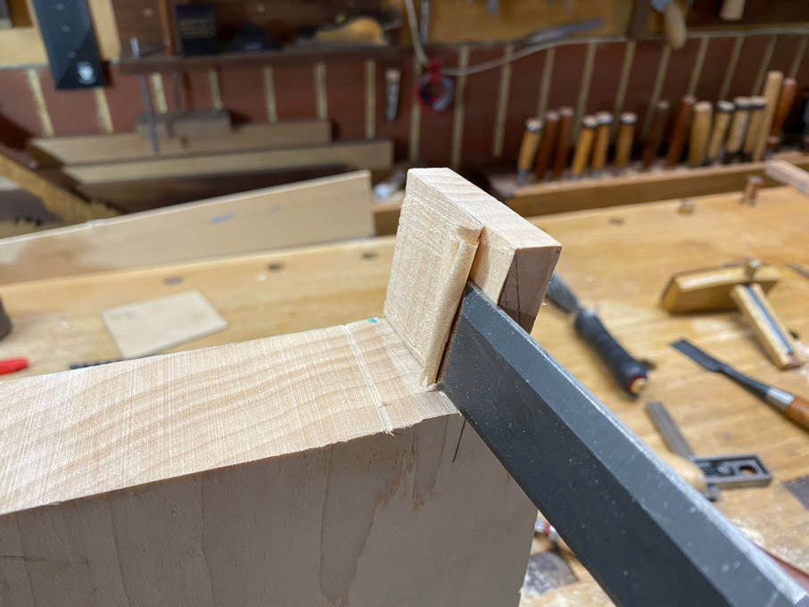
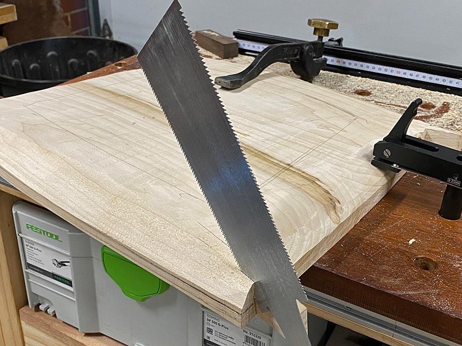
I decided that loose tenon was always a backup, and so just go for it. The saw used is a 16" Wenzloff & Sons tenon saw (10 tpi rip). It is a HUGE saw, but worked really well here with its aggressive cut.
Cutting to the line, which left just a smidgeon of waste.
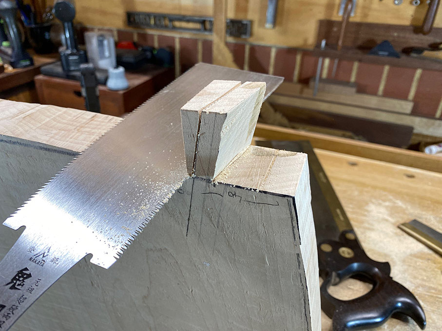
Waste removed with a Ryoba ...
All tenons cut ...
I checked several and all were on the money at 10 degrees. I'm a happy camper ...
Eight tenons and eight mortices ...
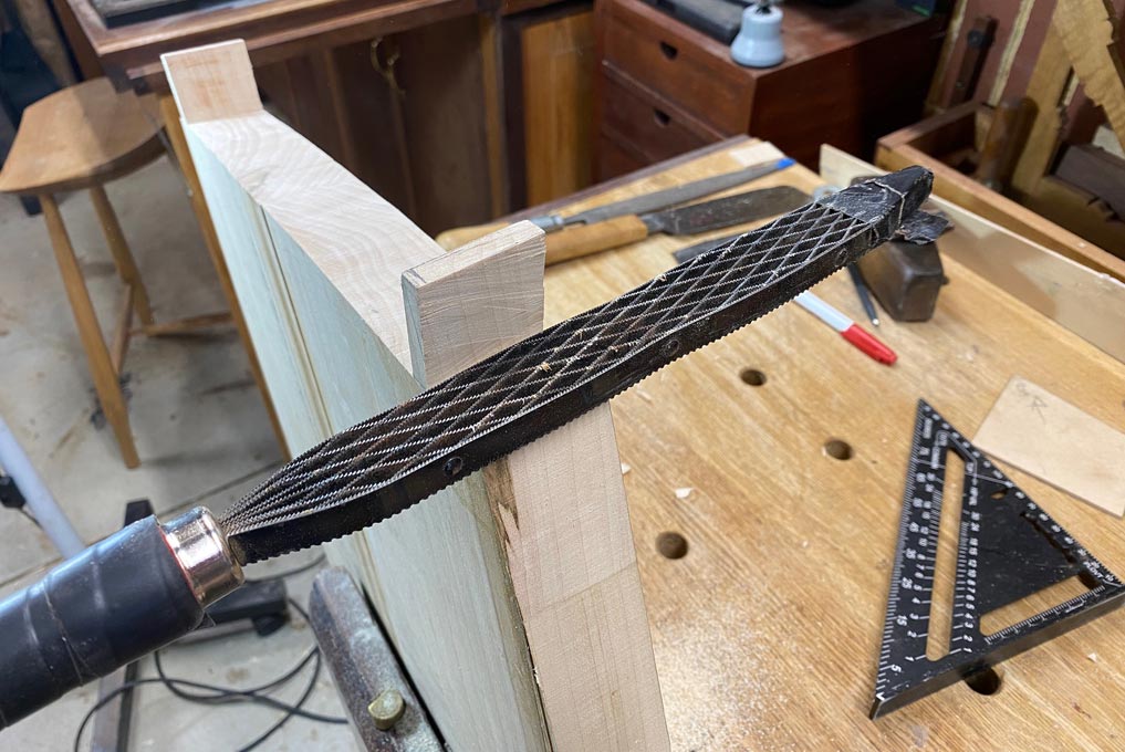
Next on the agenda: rasp the perimeter to shape, finish the tenons while there is still a flat reference (under) side, and then shape the underside of the seat.
We ended up last time with the sides cleaned up and the tenons cut to angle ...
The tenons were now sized to correct width ...
... pared ...
.. and rasped to width ..
I made a template to ensure each would later be a tight fit ...
So now we have two chair blanks with a semi-shaped outline, a profiled upper side and four sized tenons ...
Now it was back into the router sled to shape the underside, which was to curve in parallel to the upper side ...
The result was two of these, after some cleaning up with a jack plane ...
Time to give the seats their final plan shape. The seats were flipped over ..
And a template used to mark the new rear curve ..
One of the problems photographing this Rock Maple is that the light colour does not show details particularly well. Especially the seat hollows and internal curves. In addition to the upper curve, the seat is hollowed out to a depth of 18mm.
Nothing to see here. But ... from the sides ... one then the other ...
Note that the carved seat adds a 4 degree slope to the seat, which is what is in the design (however the original drawings missed it coming from carving seat, and adjustments had to be made).
We are closing in on the last lap for the seats - well, next to last lap (it seems to go on forever!). The undersides need to be shaped to remove the bulk (which was needed for the tenons), and create a sleeker presentation. Back to the Arbortech carver to remove the waste ...
I frankly do not know how many hours this saved if I had been using hand tools. I did try a razor sharp drawknife, and the Rock Maple laughed at it. The Arbortech is terrific. It does take a little while to get the feel for gentle carving, as it can run away from you if you carve with a climb cut.
Spokeshaves next, and the Veritas LA does a magic job ...
To get the best out of this spokeshave (since many described it "diving" into the wood), it is important to understand that the toe is curved 4 degrees from the mouth (as is the Stanley). Think of this in the same way one uses a travisher, which has a similar toe: The angled mouth acts to open or close the mouth. Set the blade and then adjust the depth of cut when using the body - toe down and it cuts a fine shaving, pressure on heel and the shaving is thicker. I suspect that "diving" occurs when the shaving is thicker, and attention is not given to grain direction.
The tenons are at the centre of the design. The seats started out at 50mm thick. They are down to 35mm at the centre, and will end up about 15mm thick at the surrounds. However the tenons must end up 30mm high.
Here the tenons are being "extended" from the seat, with two saw cuts ...
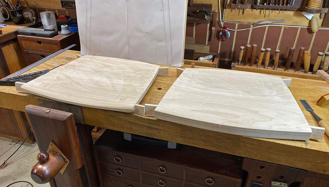
The spokeshaving of the first seat is done, and alongside an unfinished seat for comparison ...
Working on the second seat at the close of the day ...
Very interesting take on shaping the seat. Thank you for the details. Does the rasp that you used (I think it is called a shinto (sp?) rasp) need replacing very often? Do you find yourself reaching for this rasp often on other projects? Asking because I don't have a good rasp.
Don, frankly this all could have been done more easily if the damned tenons were not in the way. (Oh, by the way, that Shinto has seen a lot of use for several years, and is still going strong).
There is a good reason why so few chairs (if any!) have tenons integrated into the seats. Being able to choose the grain direction for the tenons is vital for strength. I am not happy with the run out here. My confidence in the reliability of the tenons is low, and I am making the hard decision to ditch the seats and rebuild them from scratch (!) with loose tenon joinery.
Fortunately, I think that I have worked out the method shaping the seats more efficiently, the plans have been worked out, so this is not a total disaster. Plus the existing legs can be used. Deep breath now, and get on with it.
Hmm, do you really need to start the seats all over? If you want to use loose tenons, couldn't you just saw off the integral ones and figure out how to rout mortises for the loose tenons? Seems like some sort of router jig would assure correct lineup.
Ellis, there are two options - three if I included your suggestion. But this is not possible since the seats have been carved/thinned alongside the tenons. There is no meat to sink a mortice for a loose tenon.
Option one: cut off the tenons and finish the seats. Join the legs via stretchers (using the existing mortices), and attach the seats on top of the stretchers. This is a standard method.
Option two: cut out two new blanks. Bandsaw to plan shape. Add the tenons to the still thick sides. Now carve to upper and lower profiles (as before, but without having to go back and forth to preserve the tenons). This gets one back on track using the original design. Similar to this ...
Could the tenons be reinforced with a metal rod? In an earlier picture, your template for the tenons had 10mm written on it. What about drilling a 4 or 5 mm hole and epoxy a short length of metal rod? Would that give you the strength you are looking for (countering the grain run out) without having to start over on the seats?


 Templates would have made the process easier.