Greetings everyone, Posting again after a long break.
I'm working with the Manchester Makerspace (NH) and have acquired a very old metal or pattern makers lathe. This lathe has already been used for turning and is actually a really good starting point.
I'd really like to put a variable speed drive on it with an appropriate motor (3 phase?)
Where do I start?
I'd like the speed range to be 0 to 3000 RPM (2000 is probably fine, I don't know if the headstock would be happy at 3K).
It would probably be belt drive with a single V belt - the spindle has a single V belt grove along with a flat belt (2") cone. However, I'm not against using another flat belt cone on the motor to allow multiple speed ranges.
What about pulley ratios?
My limited understanding of using a 3 phase motor with a VFD is that you can get to about twice the rated speed of the motor. How does it perform at low speeds? Really slow (<250 RPM) doesn't need much torque. I'm assuming that higher speeds would provide the rated HP of the motor.
So - what am I looking for in a surplus 3 phase motor (RPM & HP)?
What's a good drive ratio for the belt(s) motor to spindle?
Hi Dave, I think we could use a bit more info and maybe a picture or two. What kind of bearings? Is there a set of pulleys on the spindle already? What is the lathes swing? Make and model?
As others mentioned, if you provide more information about the lathe, you may get more details.
Without any information on the lathe, too many variables.
A picture of the lathe will help a great deal.
Which pulley is closest to the headstock the cone or V? What are the diameters of the pulleys?
What type of bearings are in the headstock spindle? This will influence max recommended headstock speed. Likely to be solid bronze style bearings, perhaps with oiler. If so, I am not sure about your desire for 2,000 rpm. It may depend on how good the bearings fit.
I have an old Southbend 10in swing metal lathe. V belt between motor and the motor drive shaft. 2 step V pulley. 3 cone pulleys to connect motor drive shaft to the spindle.
You need to do some calculations based on existing pulley diameters to determine motor speed. The old Southbends often used 1750 rpm motors.
I replaced my 220V 1 HP motor with 220V 3 phase and TECO VFD.
I expect your lathe may only need 1 HP, but this depends on the swing and max dimensions/weight of the projects you want to turn.
Do you have 220V available? Some VFDs can use 120V single phase input and generate 220V 3 phase output. These VFDs will be lower HP rating, e.g., 1 1 1/2 HP, since they will be designed for 15 amp max input.
Get a 3 phase motor which is designed to work with VFDs. This will give you the best performance over the VFD frequency range.
Two styles of VFD one which is fixed ratio of RPM/Hz. The other style is called sensorless vector. You will get better torque and performance with sensorless vector style.
The motor should be able to generate close to constant torque down to 15-25% of rated speed. Depends on the motor and VFD.
A 1750 rpm motor should be able to operate at higher speeds, perhaps up to 3600 rpm. I do not feel a 3600 rpm motor will be able to operate up to 7000 rpm. Things may start to fall apart due to centrifugal forces.
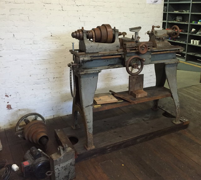
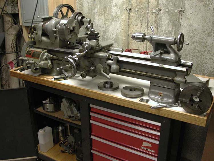
We don't know the manufacture of this lathe, it is circa 1870's. Several people that are versed in old equipment have looked and researched but have not been able to identify it. This picture shows it's original configuration (more or less).
The carriage/cross slide has been removed as it makes a lousy tool post/banjo. The lathe came with handmade wood risers for head/tail stock. The plan is to make better ones possibly out of steel or even cast. We will also make a much more functional tool rest.
As you can see from the headstock, it has babbitt bearings. They appear to be in excellent shape, no play or wobble very smooth. I have not measured the runout.
The drive for the spindle has a 3 step belt cone followed by a V grove and one more belt position (right to left from spindle). I believe the belt pulleys are 2". It also has a smaller cone outboard that I believe was used to drive the carriage feed. Interestingly the carriage drive is not threaded so you could not have cut threads with this lathe originally.
As far as swing goes, the risers we build will determine this. I'd like to get to at least 7" possibly more. One of the attractions of using this as a foundation for great lathe is that the head stock and drive can be slide on the ways to allow for outboard turning. I want to set it up kind of like a Powermatic.
The drive could be installed either above or below the ways. Could also possibly run a jack-shaft the full length under / between the ways, but that's probably not that practical.
I do have the matching drive cone with large pulley (sitting on the floor). So this lathe could also be setup more traditionally with the motor mounted on the ceiling and old style drive belts. Or with the same hanging off of the back or the lathe. However I'd really like to keep the whole thing compact (and safer).
As you can see there are a lot of ways to approach this. I also expect it to evolve over time. This is in a makerspace, we have a decent metal working / machining setup and can do more serious mods than your typical basement turner.
So:
Drive it with a single V belt or use flat belt with cone pulleys for more options?
What should top speed be with an excellent set of babbitt bearings?
I can see a headstock & riser with a motor drive mounted to the riser (again, Powermatic style). This would be simple/clean and safer than most other configurations. The motor could drive the spindle either with the V, a single flat belt or a cone and flat belt.
In general, do I want to reduce motor RPM up or down? or keep it 1:1?
A 1750 RPM motor reduced 2:1 would give a spindle "default" speed of 875. Assuming a VFD could double the motor speed, top RPM would be 1750. Which is probably fine, higher speeds are rarely used. I personally rarely turn faster than 1500 on really small stuff when using a friction polish!
It looks to me like you have a nice metal lathe that can swing 10-14 inches and 24 inches between centers.
If my guess is correct that makes the lathe too small to turn a descent size bowl and too short for most spindles. Before you put too much time and money into it think about what will get turned on it.
Almost every lathe has at least 2 pulleys to get the right amount of toque and spindle RPMs.
Horse power
10-12 inch swing = .75 HP
12-14 inch swing= 1HP
Select a pulleys for 1500 and 3000 RPM with the motor
3600 RPM rated motor running 75 hertz and 4500 RPMs
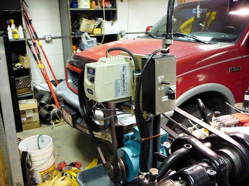
Dave, this is a great project. I found a rebuild kit on ebay and tore my 1952 Southbend down completely, cleaned each part and put it back together. I love it and enjoyed the many, many little projects along the way. And like you I wanted the ability to adjust speed, so on goes the VFD and it works great.
Your lathe is a metal lathe, also sometimes called an engine lathe.
The carriage is designed for holding tooling even though there is a woodlathe type rest mounted in it now. If you do decide to use the lathe for woodturning, removing the carriage and fabricating a banjo would make the lathe more useable.
What I noticed from the pictures are oil cups on the headstock bearings. From that I am assuming the bearings are bushing or babbitt and are likey not suitable for speeds of 3000 rpm's. Metal turning in the era this machine was used was done at slower speeds with carbon tooling. It is doubtful the top speed was above 1000 rpm.
From my point of view, if woodturning is the direction intended, mothballing this machine and finding a woodlathe would be more practical.
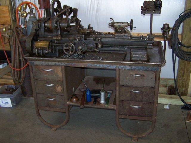
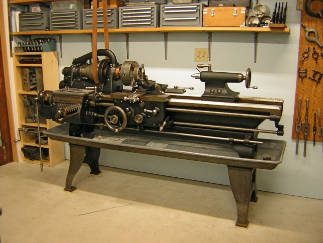
I've got the same model Southbend, about ten years younger (1962) and it was in mint condition when I got it:
I use it for wood turning on my mechanical boxes all the time. Absolutely love it. I've done some metal work but not a lot. It has the motor / cone belt drive on a hinge with a lever to engage/disengage. I've never consider changing that out but considering the annoyance of holding the belt in place when engaging the spindle I might reconsider.
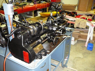
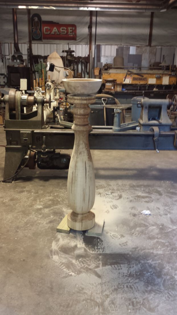
The gentleman that found the lathe for me (Jon Siegel) has done some amazing restoration jobs - check out this pic:
Yes, this lathe was not originally a wood lathe (as indicated in my original post). It was most likely or may have been a pattern makers lathe rather than a machine or metal lathe based on two features - the headstock is not geared and would have been linked to the carriage drive only via a belt. Additionally, the carriage drive shaft is not threaded. Theses features (or lack there of) was typical of a pattern makers lathe.
Regarding the bearings, I'm also aware that the bearings are babbitt. There is nothing intrinsically about babbitt bearings that makes the unsuitable for higher RPMs - check out any old industrial wood planer, it will have babbitt bearings on the cutters that had to handle high speeds and loads.
The bearings on this lathe are in excellent shape, no play, no noise and run smoothly. I don not anticipate them being a problem - most woodturning is done at speeds around 1000RPM or less. Reincarnated this lathe is unlikely to be used for spindles or small stuff.
I think you guys are misunderstanding my intentions, constraints and direction.
The lathe in question would make a lousy metal lathe - it was built as a pattern lathe, has no gearing in the head stock, can't cut threads and the cross slide is primitive.
Regarding oil ports - once the carriage is removed (already done) the only regular oil required is the head stock bearings and occasionally the tail stock. No more than proper maintenance would dictate for an older wood lathe.
I don't know about you but I routinely wax my ways when I'm turning green wood and I've never had an issue with rust.
The plan is to fabricate STURDY risers for both head and tail and build the motor drive into the head stock riser - al'la Powermatic style. Because the whole head stock assembly will slide on the ways it will then be able to swing large work outboard.
Tool rest and banjo will require some creativity along with figuring out a quick lock-down for the tail stock.
This is for a Makerspace - we have plenty of creative & inventive people around along with the ability to wield and machine (lathe, don't have a milling machine yet). However we have little or no budget.
If anyone wants to donate a Oneway / Powermatic / Robust class lathe please step forward! (we are a 501 c3 organization)
Then I could move on to build out the rest of the shop.
BTW - this lathe is also a local legacy. It belonged to and was used extensively by a well know and generous turner/teacher - Andy Motter.
I was sidetracked by the other image posted, your older model lathe would surely be a heavily
built lathe for turning wood when you have it set up. The mass of the cast iron ways and legs
would cut down on vibration and out of balance blanks when roughing them out.
Depending on your power source at your maker-space selecting a VFD that will work with your
power supply and the motor for your machine is the main concern. You can always have a motor rewound
to operate on the voltage you have available. A VFD can create issues down the road depending on the
motor and the type of bearings and the type of motor used and the grounding of the equipment. The use
of load reactors can be used to mitigate some of these issues. They also make VFD rated motors and some companies install special bearings to avoid induced shaft voltages that can be a problem on VFD driven equipment. The induced voltages on a motor shaft and bearing can create motor failure if it becomes an issue. There are grounding brushes that can be installed on motor shafts to provide a path to ground instead of having these induced shaft voltages pass through the bearings. Some of the motor companies will install ceramic bearings to mitigate these types of issues.
Your solution will require a multi-step selection process to provide a reliable set up.
Each person you talk to will have their own solution, some will work some will have long term issues.
If you can design a method of using a generic motor to turn your lathe this might make it more cost effective in the long run. If you try to re-use the existing motor mounting you might have to stay with
a particular frame size and mounting brackets designed for your machine. If you can design a generic
mounting plate for your drive motor this opens up your options for motors that can be used.
If you move your maker-space to a new location your electrical service may be different from the one
you currently have. This can require changing the VFD depending on it's line voltage rating.
VFD's are designed to work at a specific line voltage and provide a controlled load voltage for the motor.
The motor you use must be compatible with being powered from a VFD. Finding or rewinding a motor that
will work on your lathe is part of the solution. The generic mounting of a drive motor opens up your options and lowers the overall cost of your solution for the long term.
Great project David. I remember Andy well, and still use a few turning tools I got from him -- he was a really nice guy.
I bought a similar pattern maker's lathe about 12-14 years ago in Bradford, NH, that had clearly been used for wood, and a little metal spinning. I had a dream of setting up a club shop with Dustin Coates (another great guy) in the Lebanon/WRJ area, and leaving it there for all to use. A wood working business was looking at setting up a branch in Lebanon, and they wanted to host a local Upper Valley turning club, but that whole deal fell through, and they never got off the ground.
We ended up moving it to Randolph, VT for a sort of maker space there (they didn't use that term then), at the White River Craft Center. Then I moved about 30 miles further away, so the drive is now well over an hour, and I've only been back to that shop twice in over 10 years. I think it's still in storage there -- I need to reconnect with them, and either complete the set-up, or get it out of there.
Mine has 4 pulley steps, and they are turned from wood. I had intended to just turn a V-belt groove in each step to avoid dealing with 2" flat belts. Perhaps that would work for you? Maybe you could set it up with a 3ph 1 hp motor as is, and the VFD could be a good maker-space project for some smart high school kids who want to work out all the electronics? The 3ph motor should be able to take the variable speed controller as an add-on -- I think(???)
Quite a few older metal lathes were absent a threaded lead screw and change gears/quick change boxes. Some of the older machinist preferred a belt drive for carriage feed as the belt would slip under a heavy load or mistake.
To the best of my knowledge, pattern makers lathes should have a means to angle the headstock relative to the bed ways. This was accomplished in two fashions. 1) The ways were flat and a pivot held the front from moving sideways when the back could be moved about the pivot. A slot with bolt arrangement would be at the rear of the headstock. 2) If the lathe has V-ways, a sub base would be under the headstock and have a similar arrangement as described above. Method 1) is far more common.
The purpose of angling the headstock was to provide for taper (draft) in a pattern to allow for removing from the mold after packing foundry sand around the pattern.