New WoodChat!
Home Articles Forums Gallery Marketplace Videos

WoodCentral Forums

Knowledge You Can Build On — Est. 1998

This $39 jig will make you a WOODWORKING GOD!

Draw boring

Posts

Re: Draw boring

#26

And there it is !

Bob Hackett

Speaking strictly from a metalworker`s perspective this is what these tools are meant to do and exactly how they work for our craft.

Many of us who "cross trades" take what we know works in our main trade and apply it in other disciplines and materials (like stone, bone and wood for me).

One of the other things that historic texts (especially those that do not directly seek the input of journeymen in the trade) will not teach you are the "secrets of the trade". Those same texts most certainly not give you any insights as to how those secrets travel from one area of craft to another.

Any book written about the contents of a single toolbox gives you an accurate window into the mind of the person who owned that particular box and it`s contents. To say it gives us an accurate account of what an entire trade thought were "best practices" would misleading at best. If you doubt this is the case then I`d invite you to take an inventory of the joiner`s tool boxes in a single boatyard.
Re: Draw boring

#27

Re: Draw boring

joel moskowitz

All historic drawbore pins are oblique cones - never seen an ellipical one.

the round section grabs at the larger diameter of the outer cheek, turni t, and the oblique part of the cone twists and pulls the inner tenon together. I wrote up a detailed description in a blog a bunch of years ago.

If you have an elliptical section you would distort both holes. But the point is moot - I have never seen an elliptical drawbore pin but dozens of oblique cones.

Re: Draw boring

#28

Re: And there it is !

joel moskowitz

This is 100% true.

Re: Draw boring

#29

Oblique Cone

Warren in Lancaster, PA

I think you are horribly confused about an oblique cone. An oblique cone is a cone with a circular base and an apex that is not directly above the center of the base circle. That is to say the line passing through the center of the base and the apex is not perpendicular to the base of the cone. There is no such thing as "oblique part of the cone" as you mention. The whole cone is oblique.

Further if you take an oblique cone and cut it with a plane that is perpendicular to the axis going through the center of the circle and the apex, you get an ellipse. If you make this ellipse the base, then you have an elliptical cone. And if you start with an elliptical cone and cut it with a plane at just the right angle, you get a circle. Make this the base and you have a oblique cone. An oblique cone and an elliptical cone are the same except for their bases.

I have more 19th century references to drawbore pins, but if they are going to be dismissed as "incorrect" as the last one was, there is no point in furnishing them.

Re: Draw boring

#30

Yea!

Bill Tindall, E.Tn.

Another example of a picture being worth a thousand words. I see how the ellipse works.

Re: Draw boring

#31

Wow....nice solid geometry lesson

Bill Tindall, E.Tn.

....that took me back a few years to Ms. Stone my solid geometry teacher. Nice job of explaining.

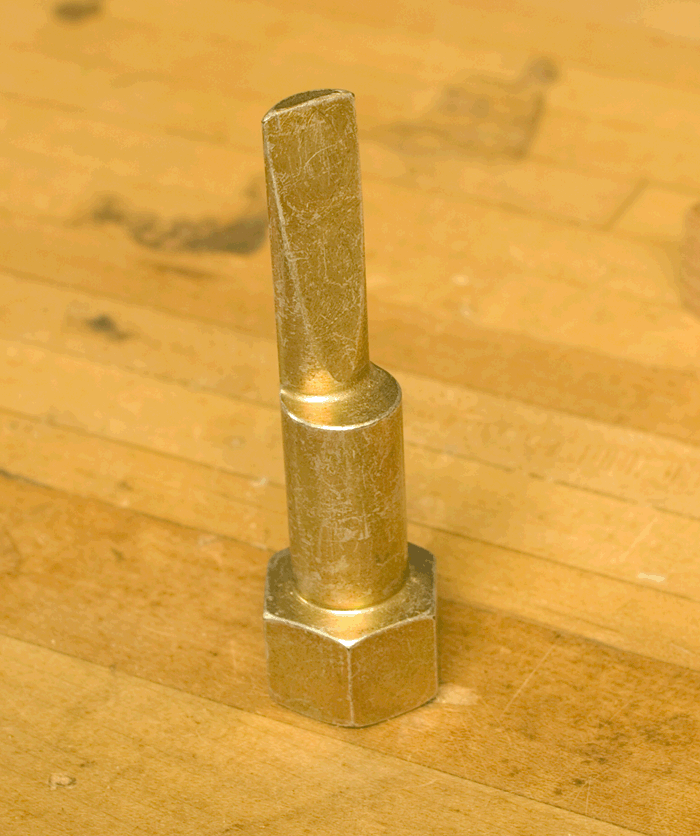
Does anyone have a good picture of the tool we are talking about?

Re: Draw boring

#32

Re: Oblique Cone

joel moskowitz

your description of the geometry is correct. But if you hold the pin vertical to the surface (ignoring the obliqueness, as you would normally because the offset is visually small, your section is circular not elliptical.

The point that is important though is if you actually take a drawbore pin, with an oblique cone for the last few inches (which is how the ones I have were made (not a continuous taper through the length - which is a shame) stick it in a drawbore joint until snug, and give them a turn they will settle a little and then pull the joint tight. If you don't have that geometry the only way to get the joint to tighten up is to force it.

Re: Draw boring

#34

Re: Draw boring pix request and geometry.

BrianMonumentCO

Joel,

Would you be so kind as to post a picture of one of YOUR draw bore pins.

As Warren pointed out an ellipse is a TWO dimensional concept.

An ellipse is the intersection of a plane and a cone.

At certain angles to the main axis of the cone it produces a circle.

While at any other angle to the main axis it produces an ellipse.

While we are at it a circle is an ellipse by definition. But has an eccentricity value of 1.

IN certain extreme angles a plane intersects a cone yields a parabola.

The circle, ellipse and parabola are all two dimensional concepts.

An oblique cone is a 3 dimensional concept.

And is not different from an ordinary cone when the main axis are aligned.

Re: Draw boring

#35

Re: Draw boring

William Duffield

I'm still (or maybe even more) confused about how your pins are shaped and how they work. I've now read your blog entry:

https://www.toolsforworkingwood.com/store/blog/78/title/How%20Draw%20Bore%20Pins%20Work

and your product description:

https://www.toolsforworkingwood.com/store/item/MS-DRAWB.XX

but a two dimensional photograph doesn't provide the understanding that actually working a pin into a joint would.

I understand and appreciate your argument that an elliptical cross section would distort the bore holes. Perhaps an oval, instead, would damage them less? I'll need to make a drawing of the shape I'm thinking, and have no idea what geometric name to apply to it. (I'll try to get back to y'all with drawings and a description in a couple of hours or so.

Maybe Bob Hackett could confirm or deny that this metal working pin that you show operates in a similar manner to the one he is familiar with?


I can't figure out how it relates. I think I see a round cylinder topped by an obliquely truncated elliptical cylinder. It also wouldn't work very well for a wooden joint because it would also do a lot of damage to the walls of the bores, but it should work just fine for steel girders.

It would be very convenient if I could try out a pair of yours at the Somerset woodworking show this weekend, but regrettably, I am not going to be able to make it to the show this year. :(

Re: Draw boring

#36

Re: Draw boring

Bill Tindall, E.Tn.

As best I can tell, given that the cross section in what I imagine to be its use position is an ellipse as Warren clearly described, it works just like your diagram. With off-set circular holes the resulting hole is approximately an ellipse. The elliptical cross section of the draw bar is rotated to drop into this "elliptical" composite hole and rotating applies force to the two halves.

That said, at $100 a piece I don't see them replacing clamps in my shop. I would argue that if a M&T joint can't be pushed together for a test fit it needs more fitting. (I'm considering a cabinet door here not a house door or a barn.)

How many are needed to be of practical use? It would seem at least 2 if not 4.

Re: Draw boring

#37

Re: Draw boring

Larry Barrett

It seems to me that elliptical pins would work. If the drawbore pin is seated so that the major diameter of the ellipse is equal to the diameter of each of the two offset circles there should not be any distortion if inserted and turned as William describes. But Joel says that the pins he has seen (and offers for sale) are oblique cones - circular, not elliptical in cross-section (cross-section being perpendicular to the holes the pin is inserted in).

Re: Draw boring

#38

Re: Oblique Cone

John in NM

He's not talking about a section taken parallel to the base as you are. The ellipse is a section taken perpendicular to the axis of the cone. In a normal cone they are one in the same and the ellipse is a circle.

Of course, none of this takes anything away from the function of the pin as you've described it, we're just debating semantics :D

Re: Draw boring

#39

Re: Draw boring

John in NM

What Joel describes works because the holes are offset and the obliqueness of the cone pulls the offset together - basically the lower (oblique) part of the pin works like a cam relative to the upper part above the mortise. Ideally the shortest line down the surface of the cone should be perpendicular to the base of that cone.

An elliptical cone pin would do the same thing, as in the drawing above, but would be more difficult to manufacture. It might also waller out the holes a bit, having less bearing area than Joel's pins.

Re: Draw boring

#40

Let me try this another way....

John in NM

Forget the ellipses - not how this pin works.

This pin works because the axis of each circle making up the oblique cone is offset from the axis of the circle resting in the top hole above the mortise. Rotate the pin and you're rotating it around the axis of the circle snug in that top hole (the non-oblique part of the pin).

This rotation makes the oblique part further down the taper describe a bigger circle - the same circle as the bit of pin above the mortise. That pulls the two holes together without having to jam a big pin through them both.

Re: Draw boring

#41

Re: Let me try this another way....

joel moskowitz

Exactly right. My real point is that there is difference in the way these work, and just a drift pin. And of course, if you have a forge they are dead easy to make, make a drift pin, heat it up, bend the tip off to the side a bit.

Re: Draw boring

#42

Re: Let me try this another way....

William Duffield

Thank you, John. Now, I think it makes sense, even more sense than the drawing I was working on, so I'm not going to bother to continue.

Re: Draw boring

#43

Now I get it, easy to replicate?

Bill Tindall, E.Tn.

Great geometry problem.

Describing how it's made did the trick for me. With the circular cross section pin engaged in the top hole- when the pin is rotated about the axis of this circle any point on the bent part below describes a larger circle, even though the pin is a smaller diameter pin at this lower point. This operation suggests that the taper of the pin and how much it is bent must be just right for the holes to be drawn.

Wouldn't it be possible to just bend a drift pin or nail set to replicate this device in a frugal shop?

I still don't get how to use it. Assuming two pins in a joint does one pull up the joint with this devise in one hole, and when pulled up, pin the other open hole?

Re: Draw boring

#44

Perhaps....

John in NM

Really I don't know, having never tried it, but it seems reasonable that one could collect a bunch of old tapered punches and start bending to get something that works well by trial and error.

The advantage of a machined oblique cone rather than a bent cone is that you can make it such that all the circular sections line up on one point of tangent - forming a line perpendicular to all the sections. That line is the point at which the holes will line up.

As to use, well, I don't use them. I'm not really fussy enough to worry about the looks of the joint, so I don't feel the need to dry fit with a drawbore pin and inspect the joint. When I do these (which is not often) I just use the wood pin to pull the joint up having dry fit it without a pin. If it's good with the dry fit it will be good or better when pinned.

Re: Draw boring

#45

Re: Draw boring for metal workers

Bob Hackett

There is a thing called a "spud wrench" which looks like a combination of "draw bore pin" with an adjustable wrench head on the big end. These are the most common example of this type of metalworking tool which is still in production today. The wrench head serves as both a wider handle which provides more twisting leverage and a wrench to cinch down the bolts once you get them in.

These tools come from the factory as a cone (picture a jeweler`s ring sizing cone). An experienced hand would take a grinder and modify that manufactured cone by cutting and then grinding the tip to fit the work being done. The newly modified tip would look like what Joel`s drawing depicts. Some workers would also grind that cone into an eliptical cross section so it can be used like William suggested to further bring difficult holes into alignment. Keep in mind that we are talking about metal rather than wood here and that you are using both a twisting as well as a prying motion to bring something into alignment that is far better at resisting deformation than most wood is.

The principles and approach remain the same, the material (wood) is just more prone to deformation and splitting. This is why you need to pay attention to the feedback from the tool rather than bulling things into place like someone hanging iron and being paid piecework rate.

Re: Draw boring

#46

Re: Draw boring

Bob Hackett

Driving the pin home distorts both the pin and the hole during the final assembly. Just don`t get carried away with the fitting and I guarantee you`ll do far less damage than the final assembly will. :D

Re: Draw boring

#47

Re: Draw boring

William Duffield

To be picky, what you describe is an oval, which is an approximation of an ellipse. In this application it would work even better than an ellipse, for the reasons you describe.


The oval is constructed from four circular arcs, two on the major axis and two on the minor axis. The curve of an ellipse, on the other hand, varies everywhere, and would therefore cause more distortion of the holes.

The larger radius arcs, which do all the work, could be machined from two off center turnings, and approximations of the smaller radius arcs could then just be ground off to remove the arises. The cross sections would be circular at the base, and more or less magnifying glass lens shaped at the tip.

But, I think I mostly agree with Bill, that it seems like a lot of money to spend for special purpose tools, when a couple of these drift pins, fitted with octagonal handles would work well enough.

http://www.toolbarn.com/hand/pounding-prying/bull-drift-pins.html