Another Norris A5 episode (*PICS*)
WoodburnBob
>
Summary: I took the lever cap off a Norris A5 so I could do some work on the bed. I then confirmed the bearing points between the iron and the bed. I did this in the hope of having this A5 perform better...an endless process. I also found a hidden design feature I hadn't heard of before and am hoping someone will tell me about its history. Wait 'till you see this!
This little HTML production probably is not worth the bandwidth. But, for those who haven't ventured to remove a pin from an infill or fit blade and bed, it might be interesting. If nothing else it may give some of you second thoughts on the sensability of your yearnings for a Norris, the postwar A5 anyway. I think this particular A5 was always out of whack in many ways...in a word, this A5 is a lemon. I suspect it's been passed around for 50 odd years as an object of desire, indeed; but I doubt any romances were actually consummated.
Admittedly, it is probably possible to do the fixes described here without removing the lever cap, but what an arduous task that would be. And, you'd never really be able to confirm what you were doing, at least not easily. So that's why I removed the cap. The A5 I'm talking about is the same one I showed with the concave sole a few weeks back (see it here if you haven't).
This little HTML production probably is not worth the bandwidth. But, for those who haven't ventured to remove a pin from an infill or fit blade and bed, it might be interesting. If nothing else it may give some of you second thoughts on the sensability of your yearnings for a Norris, the postwar A5 anyway. I think this particular A5 was always out of whack in many ways...in a word, this A5 is a lemon. I suspect it's been passed around for 50 odd years as an object of desire, indeed; but I doubt any romances were actually consummated.
Admittedly, it is probably possible to do the fixes described here without removing the lever cap, but what an arduous task that would be. And, you'd never really be able to confirm what you were doing, at least not easily. So that's why I removed the cap. The A5 I'm talking about is the same one I showed with the concave sole a few weeks back (see it here if you haven't).
| To start I use a center punch to put a divot in the center of the pin before using a drill. This will keep the drill bit from wandering and making a mess. I only do this on one side. | 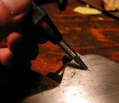 |
| Next a pilot hole goes in with a small bit, perhaps a 1/8"or so. Go down maybe 1/2" . I follow this up with a larger bit, staying away from the pin border. The purpose of this is to remove enough pin metal so that the circumference margin will collapse inward as I drive the pin with a punch and hammer. If you skip the drilling, and simply start hammering away with the punch, you have to do the reverse of peening, in the process trying to push a huge amount of steel . If there is much of a countersink in the pin hole/side plate, this will be impossible. | 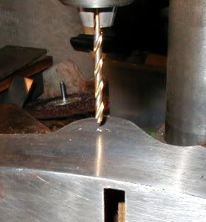 |
| At this point I've drilled my holes and given the pin about 3 moderate blows with the narrow pin punch you see here. The pin is now essentially free and is easy to push or tap all the way through and out. Total time: about 5 minutes, mostly changing drill bits, dropping them on the floor, picking them up, rubbing my back, sighing. BTW, I did the drilling on a cheap tabletop drill press. The plane was hand held, the speed was the slowest. I've also done this with a hand held electric drill...but one must be more careful. | 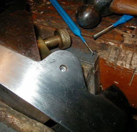 |
| With the lever cap off there is access to everything. For those who haven't seen the fixing of the adjuster, here it is: two screws. If you left the lever cap intact, I don't know if there would be enough clearance to get the two screws out and pull the adjuster...if that's what you intent was. But who would want to go through that agony. I would point out that the bed surface is rough. The varnish is orange-peeled as you see. More surprising to me is that the bed is left with saw marks. It was not planed or otherwise surfaced. Most of the other infills I've been into are smooth planed and flat. | 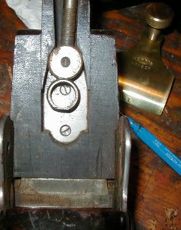 |
| Here I've simply dropped a 123 block flat onto the bed. It rocks pretty bad and dives into the front right corner with pressure. Hopefully you can see the relatively huge gap between the block and the bed on your left compared to no gap on your far right. Corresponding to this, before I started this operation I was able to shove a piece of stiff paper well up under the blade on the left side...even after the lever cap was cinched down tight! | 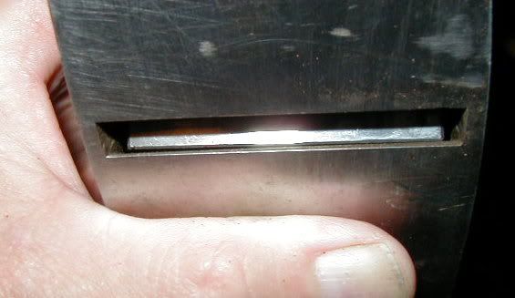 |
| Here's the 123 block resting on the bed. | 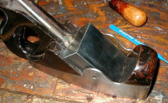 |
| Self-explanatory. | 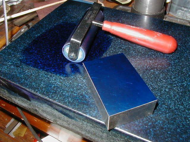 |
| Let me explain this image. I've done no metal work on the bed up to and including this image. This was blued with the 123 block. I've already used a thin wide chisel inserted up through the mouth to remove the ledge of wood towering proud to the metal section of the bed. This was what caused the worst of the "unflatness" and diving. Before removing the ledge, the 123 block, or blade, was only barely touching the far left side of the metal bed. As most of you know, the metal bed consists of the sole piece, and on top of that another piece of steel (the bevel of which here is finished with coarse and ragged end mill marks) attached to the sole piece by peened rivets. The bevels actually form an angle of something like 178 degrees, not 180 degrees. I presume this was a problem of sloppy fit and not purposeful design. If someone pipes up and says that's the way it's supposed to be, and that I've totally ruined an expensive artifact...I won't be all that surprised. | 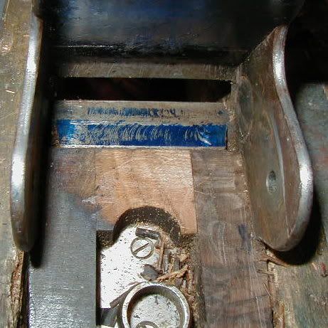 |
| By this point I've done a fair amount of bluing, filing and fitting. Now I've switched over to spotting the sole with the Norris blade that came with the plane. I think the bearing marks between the blade and the metal bed are about the best I can expect from my efforts. Remember that the bevel of the iron ends a small distance up the bed so the bluing will never reach all the way to the mouth edge. | 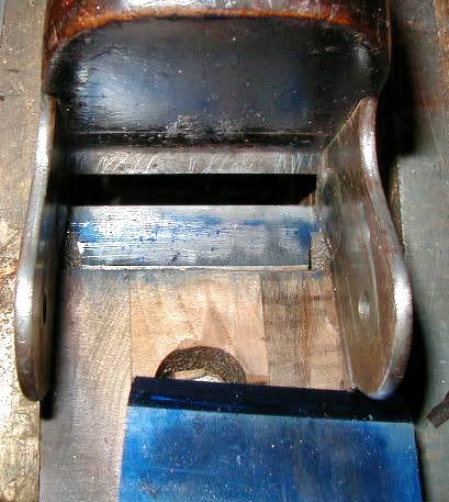 |
| This is a bit closer view. Notice the disk-like structure on the inner side wall near the mouth. There's one on the other side. With the iron and lever cap in place these are concealed. I suppose it's possible this is some sort of vestigial Victorian embellishment meant to frame and display a small cameo of your beloved on one side, and, say, your mother on the other. | 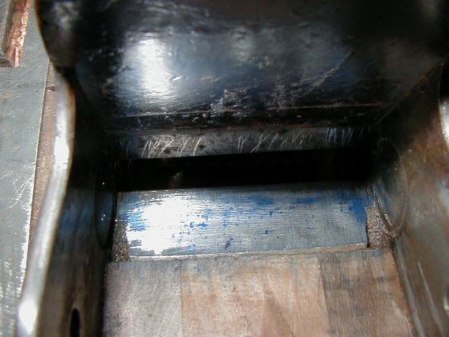 |
| In fact these are two protruding, domed, button-like swellings that narrow the width of the bed and restrict lateral movement of the blade. They are actually responsible for a snug side to side fit in this plane. Being dome-shaped, they presumably serve as fulcrums on either side of the blade and work in concert with the lateral component of the Norris adjuster...at least theoretically. This may explain why I was previously having such a hell of a time getting anything done with the lateral adjuster. | 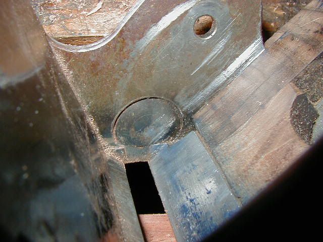 |
| At first I thought these were somehow forged or stamped into the side wall before assembly of the metal body. But I also wonder if they aren't actually rivets with very large heads set into a slightly counterbored hole. Surely, someone must know the real historical facts on this hidden feature of A5 anatomy. | 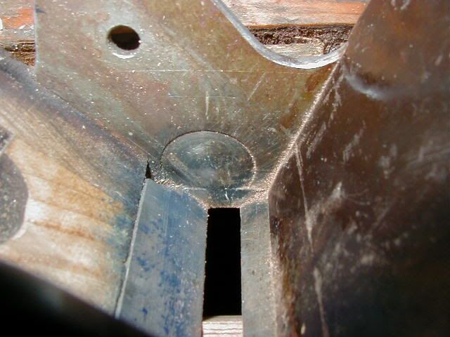 |
| As a preliminary step to finishing up this stage in my neverending struggle, I reassembled the plane using the old lever cap pin, just tapping it in. I'm not convinced I won't be opening this up again before I'm finished, so I'll put off peening a new pin in until I'm sure I won't be back. These are the first shavings. While thin, I'm not sure I'm completely satisfied with the results. There is still something wrong with the feel of it all. | 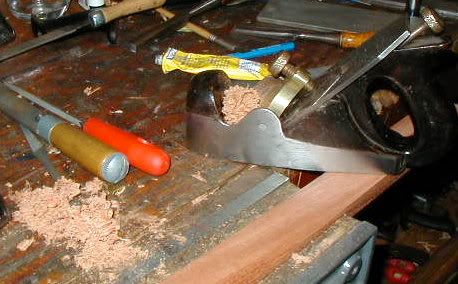 |

