Home Articles Forums Gallery Marketplace Videos

WoodCentral Forums

Knowledge You Can Build On — Est. 1998

A natural, durable finish with minimal coats and fuss popular among woodworkers, flooring professionals, and furniture makers

Freak Eye Piece Done - Almost *LINK*

Posts

Freak Eye Piece Done - Almost *LINK*

#1

Freak Eye Piece Done - Almost *LINK*

charlie belden

Still have to figure out why the piece works as intended when connected to a computer - but behaves differently when run off a 9V battery - required to hide the micro controller and servo inside the piece. That should be solved in the next few days.

Tried an idea for an unusual finish on this one - because it seemed appropriate for this piece - about amphetamines, methamphetamines specifically - Crystal Meth.

The capsule was primed white, shot with high gloss white, given a coat of 3M spray adhesive and then "dusted" with tiny glass Bead Blasting beads. The effect is coarser than a Powdered Donut look, but finer than a Granulated Sugar look - more like an Ice Frosted look. In the right light, at certain angles - the surface glows - like the stripes on the street - in your headlights.

This is an editorial piece about a subject I was introduced to while working with a group called Drug Crisis Intervention - the need for On Demand Drug Rehabilitiation. Back then, amphetamines were in Diet Pills, and women, typically young women, were unknowingly getting strung out of Speed and would call looking for help - often at 3 am.

At the time Drug Crisis Intervention, a volunteer organization, was the only help available. Mainly college student volunteers, we did what we could to provide help and information. Through the years I continued trying to help addicts, usually heroin addicts but later crack users and meth users. Trying to get them help was truly a frustrating excercise in futility - even for someone who has their wits about them and experience with dealing with bureaucracies.

Fortyy years later - things haven't changed - for drug addicts in general - and speed freaks specifically. And the social priced tag of not having On Demand Drug Rehab is enormous. We build prisons instead of Rehab Facilities. And the cost to addicts' families and friends can't begin to be "monetized".

This piece is intended to disturb in hopes of raising awareness of a real problem in our society - and propose a solution, or at least a better way of dealing with drug users / abusers.

Houston - WE have a problem.

Comemnts, suggestions, questions and constructive criticism welcomed.


YouTube vid of Freak Eye

Re: Freak Eye Piece Done - Almost *LINK*

#2

Leo Cuellar

Re: Freak Eye Piece Done - Almost

Leo Cuellar

Hi Charlie, its looking better each time! Are you going to build a larger pedestal underneath to house the controller? If you feed the wiring in from a central point it might give it more room to do its jitter, if you give it a little extra space between and don't make the mount solid. Just my 2 cents.

Leo

Re: Freak Eye Piece Done - Almost *LINK*

#3

Re: Freak Eye Piece Done - Almost *LINK*

charlie belden

Leo:

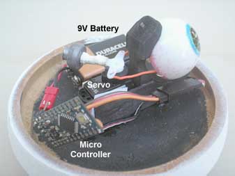
The micro controller visible in the video is the one I used for prototyping component wiring and software debugging. It's larger, with sockets for plugging in components quickly and easily. The micro controller for this piece is much smaller - 1 3/4" long, 3/4" wide and maybe 1/16" thick - and wires are soldered to it rather than plugged in. The side of the 9V battery I'm trying to use to power it is longer than the micro controller and about it's width. Two pennies touching edge to edge is about the size of this little thing.

For this piece to work as I intend it to, the electrical and mechanical all have to fit INSIDE the piece - out of sight - a stand alone piece with no external wiring.

The challenge/mystery I'm working on is finding out why I can get the micro controller to make the servo work as I wish it to - when powered off a USB cable connected to my computer - but when disconnected from the computer's power - results in completely different servo behavior when powered from a 9V battery. Should have that solved in the next day or so.

I'm still on the steep part of the learning curve of micro controllers and programming them and there are bumps along the climb. What I hope to be able to do is put together a Tutorial For Turners that'll flatten the learning curve for The Next Guy/Gal. I also will be including a heavily commented copy of the program used as well wiring diagrams with part lists, part numbers and ball park prices and sources - that show what connects to what. So pieces I do can also serve as tutorials for using a micro controller to add behaviors to turnings.


img

Innards

Re: Freak Eye Piece Done - Almost *LINK*

#4

Re: Freak Eye Piece Done - Almost

bernie feinerman

Have you checked what the effect of the internal impedance/resistance is of the battery compared to the USB port?

Bernie

Re: Freak Eye Piece Done - Almost *LINK*

#5

Re: Freak Eye Piece Done - Almost

charlie belden

I'll be checking to see if the voltage between the servo's black and red wires is the same when powered from the USB port and when powered off the 9V battery. Then I'll do the same for the voltage between ground and the micro controller output pin that controls the servo's movement.

I thought all versions of Arduino micro controllers functionally were the same. May be that the little MinoPro doesn't have the voltage regulator its bigger cousin I used for prototyping has. I'm no electronics tech. I had a physics class on Electricity and Magnetism and an EE Circuit Analysis class way back when - just after electricity was discovered. Wasn't around for the invention of DIRT - sigh.

There's a thriving community of folks playing with the Arduinos who are a great resource for newbies like me - kind of like this community if for turners. Someone in the Arduino community will answer my plea for help and solve this current problem.

Re: Freak Eye Piece Done - Almost *LINK*

#6

Leo Cuellar

Re: Freak Eye Piece Done - Almost

Leo Cuellar

Charlie, thanks for letting me know what the state of your project is. Wish I had some help for you, but electronic talk literally makes me sleepy. In fact I usually fall asleep in front of the TV :D Mechanical is more my forte. I do enjoy your progress reports though... it is always good to see somebody pushing boundaries in such a creative way!

Leo

Re: Freak Eye Piece Done - Almost *LINK*

#7

HOW?

charlie belden

Passed a physics Electricity & Magnetism class and an EE Circuit Analysis class - 40 years ago.

Have run 220 from the electrical panel at the house out to a panel in my shop and wired up

my shop from that panel - switiches, 110 quad outlets and 220 outlets.

I know what resistance is, its units are ohms and how to measure it with a VOM. Impedence?

I think it has something to do with impeding the flow of current. What to measure and how

to measure impedence? No clue.

I've got a USB/TTL cable to connect the MiniPro micro controller to my computer, a 9V cell

with a connector I can plug into two pins on the MiniPro, "RAW" and "GND" and wires from

the "Vcc"m GND and Pin 9 on the MiniPro to a connector that plugs into a connector on

the Servo.


What now coach?

Re: Freak Eye Piece Done - Almost *LINK*

#8

Re: HOW?

Jeff Myroup

Impedance is found in AC Circuits. It is a trig function of Inductive reactance, capacitive reactance, and resistance. I don't think you can actually measure it

Re: Freak Eye Piece Done - Almost *LINK*

#9

Re: HOW?

bernie feinerman

USB voltage ports are nominally 5 volts and can (or so I am told) be as low as 4.35 volts.

USB ports in PC's can supply 0.5 amps and some 0.1 amps.

Have you try to run your servo from a 6 volt battery or 3x 1.5 volt batteries in series?

You have said that your servo works when connected to a USB port and behaves differently (which I assume means not the way you want) when operating from a 9 volt battery so the difference may be due to the internal characteristic of the battery, or due to the regulator circuit that drops the 9 volts down to the servos operating range.

I have a IBM/Lenovo laptop and after several years, it now it will not complete booting up if, both a mouse, and a flash drive are both plugged into its 2 USB ports. Once it has booted, I can plug in my flash drive and the computer is happy! The point is that the USB port supply can vary during the PC start up cycle and with age. Someone smarter than I can perhaps explain this situation. Perhaps this relates to your problem.

One way to much internal resistance would be to put a small value resistor in series with your power source, (both the 9 volts and the USB port) and measure how much current is flowing in each case (in this case the current would be the measured voltage divided by the value of the resistor). The value of the resistance should be low as to not drop the output voltage significantly. You could measure the current with a milliameter which would be less complicated.

I am not all that sure how knowing the internal impedance will help you but you do need to track down the difference. If you can find a battery voltage that keeps your servo happy, you can then worry about how to find a miniature version of that battery.

Do you have a schematic diagram of your servo that lists the internal parameters?

What is the model number of the battery that you are using?

Have you tried using a larger capacity version of your 9 volt battery?

Re: Freak Eye Piece Done - Almost *LINK*

#10

Re: HOW? - 2

bernie feinerman

After rereading the entire thread, it seems logical (to me) that the 9 volt battery is coupled to the servo through a voltage regulator to make the 5 volts that the USB port supplies.

The servo, since you are getting motion, implies (again to me) that there are solenoids, or little motors, that are activated in response to the servo commands. Solenoids and motors, whenever energized each time, will draw more current (aka - starting current in large motors which can often be multiples of running current) then after they are energized.

I think that the combination of the impedance/resistance of the voltage regulator circuit and the small battery you are using to generate the working servo voltage are not capable of handling the momentary current drains of the servo so that the nominal 5 volts that the servo expects drops momentarily. You might be able to see this effect if you have access to an oscilloscope (if they still make them) connected across the lines to the servo - after the regulator.

If I am right (or close), you ought to get better results using a LARGE 9 volt battery.

Your turn.

bernie

Re: Freak Eye Piece Done - Almost *LINK*

#11

Solved - I think

charlie belden

A solution to my problem was to attach the Red (+) and Black (-) leads on the servo directly to the RAW pin the (+) side of the battery connects

to the MiniPro PCB (Printer Circuit Board) and the servo's Black (-) to the GND pin the (-) side of the battery to the GND pin on the MiniPro PCB (Printer Circuit Board). The servo's Control Signal wire - yellow - is the only wire the micro controller uses to control the servo arm - and that's with just a tiny amount of electrical current - 0.02 MILLIAmps.

Will see about posting the video of me doing my Happy Dance! ; )

On second thought . . .

Next up - Stepper Motors. Oh boy! Oh boy!

But first - I'm going to get all these wire, and wire cutters and needle nose pliers and pieces of shrink tubing and soldering iron, solder and thrid hands, PCB vise, breadboards, jumper wires, multi meterSm battery packs and computer cables - OFF MY DESK!

Re: Freak Eye Piece Done - Almost *LINK*

#12

Re: Solved - I think

bernie feinerman

Sounds like you have a practical solution.

How much current does the servo draw in operation?

Kinda dumb question - How long will the battery last in operation?

Re: Freak Eye Piece Done - Almost *LINK*

#13

Re: Solved - I think

charlie belden

According to the $50 digital multimeter I got just to find out, the servo draws between about 8 and 32 milli amps on the Red leg of the servo ("about" because the servo is moving the servo arm randomly between 65 and 115 degrees (90s being Straight Ahead) and the delay between moves varies randomly between 50 to 500 milliseconds. The servo's Yellow control line draws only about 0.02 to 0.04 milli amps.

The servo has run as expected off 2 AA batteries and one 9V battery. How LONG they keep the servo going? That one's unanswered. Lithium Polymer batteries can give me more amp hours - they're lighter and they can be shaped to fit around things - important when space is a problem and I think I can recharge them - in the piece.

This servo took more effort than I'd thought. But the next piece using a servo will be easy - now that I know what I was doing wrong. And if the stuff I put together about using micro controllers helps The Next Guy avoid making the same mistakes - and get to playing rather than studying and trial and erroring . . .