
Obnoxiously Long Post but here goes
Alan Young
This post probably exceeds being obnoxiously long- but starts from the beginning of a project of which I posted previous progress pictures of but haven't updated in many weeks so it seem best just to start at the very beginning. This post shows the progression from design to completion of a pair of music stands.
Some late weekend afternoon last August I was sitting on my front porch with my oldest son when my cell phone rang. I looked at the number and didn't recognize it all and just about let it go to voice mail but instead decided to see what the call was about--It was gentleman inquiring about the design and commission of a music stand. Our initial conversation was brief as I told him I was about to be away from my shop for a couple of weeks but we could resume discussions when I got back.
This kind of delay can frequently mean the end of a party before it even gets started, but I was happy to hear back from my client After several months of phone conversations and e-mails exchanging renderings and ideas we co-designed this stand for the Salmagundi Club of New York.


Of the many details and features of this stand design of particular note is the Desk Angle adjustment Mechanism and the Brass Medallion Logo of the Salmagundi Club


I began work on the stands with fabrication of the brass pieces. The Desk Angle Adjustment Mechanisms are first.
In my previous Music Stands I built an adjusting mechanism similar to music racks found in Grand Pianos.
There was a significant drawback to this design-If there was a manuscript with too much weight the whole rack could tip forward unless it was on the farthest back setting. So I set about to design a mechanism that would allow for adjustments but lock into place. After many hours at the drawing board I settled on this
Spring Loaded Pull Pin Design

After an number of hours in the machine shop I produced the parts for each DAAM

The main Block is connected to the Rising Pole with a 1/2 steel rod. The rod is fixed to each piece with a 1/4-20 set screw.

Here are the parts to the Spring Load Pull Pin and Pull Pin Mounting Block.

The Pull Pin Block houses a spring loaded brass Pull Pin


The Pull Pin Block is then mounted to the main block.

The Outside Knob is attached to the Pull Pin

A Cover Plate is mounted to the opposite side of the Main Block


I then moved on to fabrication of the G/F Clef pieces for the height adjustment pins. The profile is secured to the brass with double sided tape. I drilled out the enclosed areas with an end mill.

Then I moved to the band saw and cut around the profile

After the profile is outlined it's file file file and sand sand sand.

I looked into having these pieces outsourced through a 3D printing process but decided in the end to make it myself. I drew up a design on the computer-printed it out and glued it to the surface of a brass plate. I then free hand milled out the profile and refined it with lots of hand filing and sanding.


Ellis Wallentine was watching my process and suggested the relief profile would benefit from a contrasting background so I mixed up some black epoxy and filled the relief with it.

Here is the medallion after the second round of epoxy fill

Here is the entire structure that gets mounted to the post

The medallion is mounted opposite the Height Adjustment pin.

After a great deal of filing and fitting the pieces formed and set into the posts

Next I moved onto the fabrication of the Tri-Pod Bases.A great deal of time was spent coming up with the final base design. This design is simple looking in shape but requires careful planning in the execution of the fabrication process.

My original plan called for 1/16th Anigre veneers to be glued over a form. Then trace a pattern over the glued up lamentations and cut out the base in one solid lump.

I went so far as to make the form and begin the lamination process but it didn't take too long for me to question whether this technique would yield a piece that was solid and strong so I abandoned this plan and pursued a modified solid wood design that I had used in a couple of earlier stands instead.
This is the profile of the leg.
The initial cut yields a shallow domed waste piece.The "waste" is used by gluing it to the top of the board


The final cuts on the band saw yield the tripod

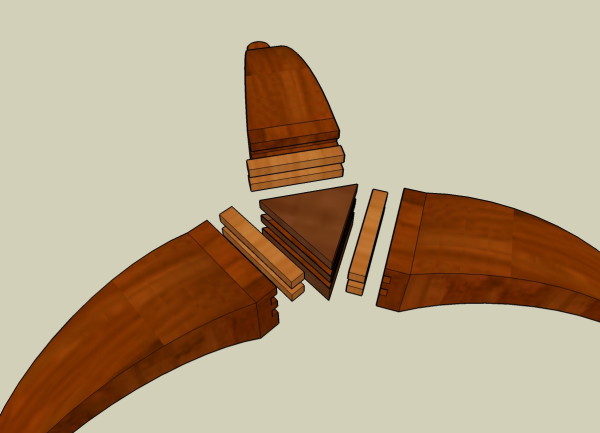
I glued up triangles where the three legs will meet and be joined with loose tenon joinery.

Next-The legs get dadoes cut for the matching joints.

All the joinery has been cut- The grooves will be filled with loose tenons for the joint.

Each loose tenon is cut to size. Cleats are screwed to each leg so there will be something for clamps to bare pressure against.

A two-part epoxy will be used to glue the assembly together

Somewhere under there is a three legged base

After the glue sets-(at least 24 hours) I start the process of refining the profile and surface of the structure- lots of hand filing and sanding,


After all this effort I was still not sure of the long term strength of these pieces-especially at the narrow transition point from the arch to the foot. So I made further modifications-I added a round plywood layer under each foot-hen cut dado grooves from the under side and epoxied plywood splines into the grooves to provide cross-grain strength.


I added longer splines under each arch. I cut grooves with a router and hand chisels then epoxied plywood splines for an "I-Beam" type of reinforcement.

I started the layout and cutting of the pieces for the desks.

Time to glue things up-I am using a two part structural epoxy. It takes 24-36 hours to set and strengthens further over 48 hours.

The two columns are epoxied with splines for strength and alignment.

I roughed-out the turnings of the columns.

Working on the hardware that will secure the turned columns to the tri-foot bases.I fabricate a rectangular block from aluminum that will be a plug in the bottom of the turned wooden column. The block is drilled and tapped for a 1/2"-13 bolt/threaded rod. After the bolt/rod is threaded into the block-a second hole is drilled and tapped for a 1/4"2- screw-rod.


I will cut of the hex head from the bolt then it will run through the Tripod base and be tightened with a plate and nut.

Each of the desks has eight brass rods 1/4" in diameter set into the mid section. They are inserted through holes from the underside of the desk and the holes are capped by a brass plate.

These piece are made to capture the 1/4 inch brass rods. The rods are inserted in the brass and press fit the tapered upper pieces into the wooden desk frame.

The lower pieces have a 1/4 Inch through hole with a knurled end and tapped end. The tapped end is screwed into a 3/8Inch tapped hole in the lower section of the desk frame.


The rods are inserted in bottom of the Desk through enlarged holes. The Brass Rods are pushed tight into the framework and then wooden dowels are cut to fill the opening.


A Brass Plate covers the assembly
The brass pieces for the feet have a cap and a pad. They are connected by a 1/4-20 screw that runs through each foot end.


The finishing process begins with a coat of glue sizing-Thinned hide glue is applied to seal and fill the surface.


Then each surface is sanded and a primer applied

Then a series of coats of Black Lacquer


Here are the stands photographed in my neighbor's home before they were picked up by their patron on Sunday and left for New York


The stands will be presented to the Salmagundi Club tomorrow.
Thanks for ready my novel.
-Alan

 Thanks, yeah that's heavier than I want the whole project to be.. It does appear that some parts may still be usable in concept.


