Home Articles Forums Gallery Marketplace Videos

WoodCentral Forums

Knowledge You Can Build On — Est. 1998

This $39 jig will make you a WOODWORKING GOD!

A dowel jig for turned legs...

Posts

A dowel jig for turned legs...

#1

Alan Young

A dowel jig for turned legs...

Alan Young

>I have been working on and off on a desk. The desk has turned and fluted legs.

Some time back I posted pictures of jig I built to run the grooves in the legs. As I resumed work on this project this week I realized I had somewhat design myself into a corner- or at least into my basement shop...The legs I had made were not yet attached to the upper case because the case work is still in the construction stages. Ideally, each leg would have been one large piece- from the turned section to the upper square section that joins to the case work. But my lathe would not hold a turning that long. So I designed the leg to get attached to the case work via a dowel...

This plan was short sighted too. If I were to have glued doweled legs into the case work, the resulting desk would have been to big to get through the doors of my basement shop....So I was forced to design the legs as "removable". A idea which in the end is probably a better plan anyway-as removable legs will aid in negotiating tight corners. So the plan now is to glue a threaded rod into the end of the legs and a matching threaded insert into the corresponding section of the casework.

Back to the turned legs-whether I was to glue the entire leg to the upper case work or proceed with a threaded rod, I still needed to drill a hole through the top of the legs. Now I was face with another dilemma. I have a bench top drill press that is not big enough to accommodate the length of the legs, Neither is my nifty-recently acquired Mill/Drill... So I have to drill the hole "free hand"...This of course requires a means of making sure the drill is parallel with the leg. So I came up with this little jig.
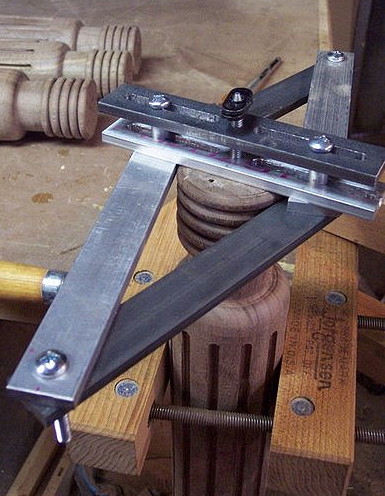

The jig is more or less-self centering with a 1/4-20 screw turned to a point as the centering pin.


The jig is placed on top of the turned leg. The centering pin is set in the hole that is left from the lathe nut.(of course this ENTIRE jig would have been unnecessary if I had thought to drill the holes while the legs where still square stock!)
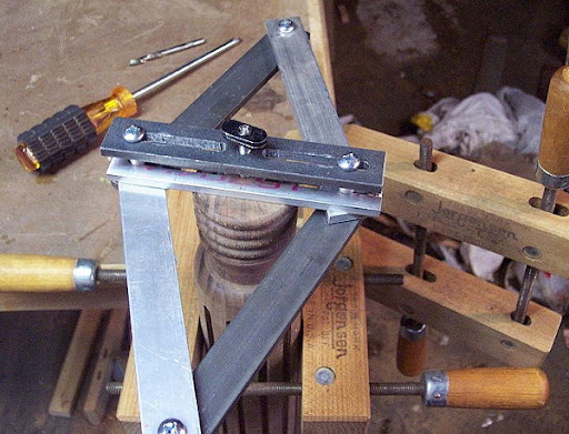

But here we go..Then the jig is closed tight against the leg as two opposing pivot points move along the slide bars.


At this point all the screws are tightened and the jig is held firmly in place centered over the leg.
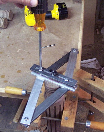

The upper and lower slide bars each have a centered 1/4 inch hole. These are space about 1" apart and form the parallel line for the drill to follow into the leg.
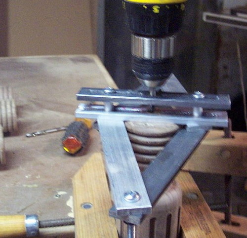

A bit of tweaking could be done but the resulting hole was "acceptable" :^)...
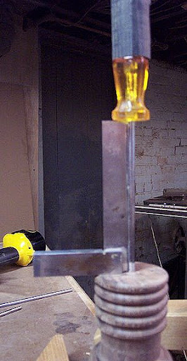

After the four legs were drilled for a the 1/4 inch hole I enlarged them to 3/8. The 3/8 drill easily followed the smaller diameter hole.


I will probably continue the precess up to a 1/2 inch and then insert a threaded rod....

Thanks for looking....

Alan


img

Re: A dowel jig for turned legs...

#2

Alan Young

uumm...the pictures seam to have disappeared!

Alan Young

>At least in my edition of Firefox.

Explorer has them running...weird.???

Alan

Re: A dowel jig for turned legs...

#3

Not working on I.E.6 or Firefox 2.0.0.14

Don in Northern Arizona

>

Re: A dowel jig for turned legs...

#4

Re: A dowel jig for turned legs...

Kneale Brownson Dreaming of the Snow in N. MI

>I'm getting them to work by right-clicking on each red X, selecting properties, highlighting the URL and cut'npasting the URL in the browser window (IE7). After viewing the image, I hit my back button and the pix appears in the message.

I'm wondering if there was an error made in the insertion of links to the pix???

Re: A dowel jig for turned legs...

#5

Alan Young

Well now I have them back...Very confusing..

Alan Young

>

Re: A dowel jig for turned legs...

#6

Ellis Walentine

Interesting knockdown problem

Ellis Walentine

>All your images are stacked in this post, but the only one that shows up for me in Firefox is the one of the jig sitting on top of the leg. In IE6, only the end view of the four legs on your bench shows up. When I paste the individual URLs of the images into my IE6 browser, they show up, but not in Firefox. There, the browser asks me if I want to open them with my photo application.

We've not had trouble with calling multiple image URLs here before that I know of, so I'm wondering if this has to do with the site where you are storing all these images, or maybe with the length or formation of the URLs themselves.

I wish I could help, but the best I can do would be to save all the images here on WoodCentral and change all your links to them directly. If I get a chance I will try that, but if I'm going to go to that length, we should probably make it into a shop shot or an article for posterity.

Regarding the jig itself and the idea of attaching a leg with all-thread, I had a couple questions. First, I'm wondering how you can be sure the jig is square to the leg, when all you have is a narrow strip of metal sitting on endgrain that may or may not be exactly perpendicular to the axis of the leg. I guess it'll be close enough, but it doesn't strike me as the most mechanically sound way to drill this hole, not that I have any particular insights myself on this, and I've never had much luck when I've attempted similar operations, as with lathe tool handles and such. Maybe some of our machinist folks will suggest a good method. OTOH, the alignment might not be so critical, because the important thing is that the mating endgrain faces both be perpendicular to the axis of the leg/endblock assembly. When you crank the all-thread home, it will probably be able to deflect enough to allow this joint to pull up tight; at least, that's what you hope will happen.

Another question has to do with the notion of a threaded insert for a 1/2" thread. I've never seen or used one of these, but I'll bet they're a bear to insert. I think I would be inclined to epoxy the threaded rod into the leg, several inches deep if possible, maybe even with a metal cross pin somewhere to keep it from turning, and then somehow hide a captive nut in the corner block to receive it. I think that would even be stronger. Did I mention that I always try to over engineer things?

Nice project, by the way. Very ambitious and shaping up nicely from all appearances. In retrospect, I probably would have borrowed someone else's lathe at the outset and avoided the whole issue of knockdown construction.

Ellis


Re: A dowel jig for turned legs...

#7

Alan Young

Re: Interesting knockdown problem

Alan Young

>Hey Ellis--

I think the picture problems lie with Google-I have been placing web photos there recently as my own webpage is getting too full. I guess I need to edit out some stuff....now to your excellent observations...


Regarding the jig itself and the idea of attaching a leg with all-thread, I had a couple questions. First, I'm wondering how you can be sure the jig is square to the leg, when all you have is a narrow strip of metal sitting on endgrain that may or may not be exactly perpendicular to the axis of the leg.

I guess I am counting on the accuracy of the original cross cut I made to the leg(s) when I cut them to length-I either used my SCMS

or I used my miter gauge with a backstop on my table saw so that all legs where garunteed the same length. I hope I would have made sure the MG was 90 degrees to the sawblade. It's probably been two months since I made those cuts I really don't remember how I made them but the hope is that the blade was perpendicular to the leg. But I suppose even if it was there is no guarantee that I had set the legs perfectly true in the lathe itself. If either end was not precisely centered then my top (x)would not be 90 degrees to the length(z).....


I guess it'll be close enough, but it doesn't strike me as the most mechanically sound way to drill this hole, not that I have any particular insights myself on this, and I've never had much luck when I've attempted similar operations, as with lathe tool handles and such. Maybe some of our machinist folks will suggest a good method. OTOH, the alignment might not be so critical, because the important thing is that the mating endgrain faces both be perpendicular to the axis of the leg/endblock assembly. When you crank the all-thread home, it will probably be able to deflect enough to allow this joint to pull up tight; at least, that's what you hope will happen.


Yup it's a hope at this point....and one that will have to wait to see it's result....


Another question has to do with the notion of a threaded insert for a 1/2" thread. I've never seen or used one of these, but I'll bet they're a bear to insert. I think I would be inclined to epoxy the threaded rod into the leg, several inches deep if possible, maybe even with a metal cross pin somewhere to keep it from turning, and then somehow hide a captive nut in the corner block to receive it. I think that would even be stronger. Did I mention that I always try to over engineer things?

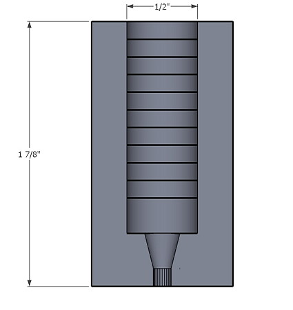
That's the plan Ellis. I intended on fabricating my own "captive nuts" ie-threaded inserts. They will look like this cross section...only probably 3/4" OD rather than the 1" OD shown here. The nut is actuall upside down in the drawing as it will be placed in the blocking of the casework-Held in by epoxy and a screw driven all the way through..


The legs will get the threaded rods- epoxied in as deep as possible. I thought about a cross pin to keep the rod from spinning-But there is now guarantee that rod will be hidden from view when the leg gets spun on- or that it will line up in a perfect position in front to look like a design intention....Or is there a trick to turning things that can guarantee such a result????

Anyway here are a couple of shots with the front legs loosley clamped to the corner bracketing and the drawer framing.


Nice project, by the way. Very ambitious and shaping up nicely from all appearances. In retrospect, I probably would have borrowed someone else's lathe at the outset and avoided the whole issue of knockdown construction.


The engineering problems /challenges are magnified because of the time delays I have incurred while working on this piece. It's a noncommissioned desk and gets attention when I can squeeze in the work. Not a good situation because I tend to forget my plans and intentions-even with drawings....

C'est la vie..:^)

Alan

Re: A dowel jig for turned legs...

#8

Ellis Walentine

Couple things...

Ellis Walentine

>I think a barrel nut would be simpler to make than the thing you drew there. Just take a piece of 3/4"� mild steel rod, drill and tap it perpendicular to the axis for your 1/2-13 thread, and drill it into the corver block from the side. A spot of hot glue or epoxy will hold it in place.

And regarding pinning your all-thread into the legs inconspicuously, just make the pin short enough that you can set it in from the leg surface, so you can plug the hole with a bit of wood.

Ellis

Re: A dowel jig for turned legs...

#9

Re: Couple things...

Barry Irby

>I completely agree with Ellis.

I built a bed for my son and used home made barrel bolts to attach he rails to the head and footboards. Used 3/4" mild steel form the Borg, drilled and tapped them for 3/8" bolts. Buried them in the legs. Put some oil on the threads and poured some epoxy into the holes to fix them in the exact position. I bolted the rail in momentarily and added the epoxy and let it set. That was to index the barrel bolts in the holes so they would not float around.

I would epoxy the all-thread rods into the legs and after it set, I would assemble the upper and lower legs. Snuggley, but not so tight as to extract the All-thread. Then I would mark a spot on the inner side of the lower leg and drill into the leg and through the All-thread and seat a pin in it and plug the hole with a bit of wood.

I use 3/8" bolts on my son's bed and it was as solid as if it were a single piece of wood. If you center the rod in the leg as you are doing it will be functioning mostly in tention, not so much in bending. Drilling a half inch hole through a 3/4" rod does not leave much on either side. That's why I went with 3/8" bolts.