WoodCentral
❌

Normal view

Danish Loveseat: Part 3

24 June 2025 at 03:18

Backrest and Seat

In my last post the parts and pieces were completed for the seat frame and the backrest. Since that time the slats were finished (Osmo 3043 using Mirlon abrasive pads). The top and bottom rails were finished as well but their tenons were taped off. The final step was to form the sides of the backrest with spokeshaves then glue the entire piece together and finish it completely. Before assembling that though the through mortise and tenons for the arm rests had to be fitted.

  • Trial fit for armrests
  • Backrest pieces prefinished
  • Backrest glued up β€” 6β€² Jorgensen clamps

The process for making the seat assembly was similar. It consists of two end pieces which are supported by the stretchers between the two legs. The front rail is attached with a haunched mortise and tenon joint and the back and center support use mortise and tenons as well. To accommodate the webbing from House2Home, a 1/8 slot is routed for the clips. Kind of tricky, it’s best to remove about 1/8 of material so the webbing lays flat. This was done on the tablesaw with a rip blade which requires dropping the wood onto the blade and then lifting it off β€” care required on this operation. The recess is then squared off before I assembled and finished the entire seat.

  • Haunched tenon on front rail
  • Material removed for webbing, rip blade
  • Squared off and chiseled smooth
  • Glued and clamped
  • Finished with 2β€³ webbing installed

Armrest to Leg Assembly

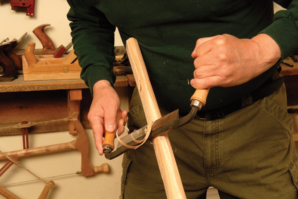
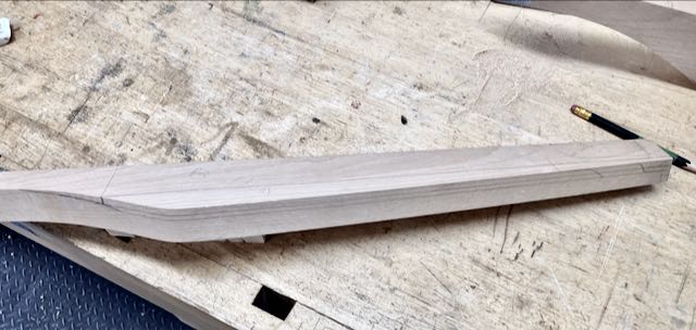
While designing this piece I looked at so many Danish Modern pieces on Pinterest it made my head spin! I wanted something graceful and not just a machined, routed piece. I had set aside a piece that had some interesting grain for the armrests so that determined how wide they could be. Even though they’re about 4β€² apart it’s important to me that the grain matches. The bottom has a simple, long chamfer while the top has a slight radius. Sculpting began with my old Stanley 151 and finished up with a Bogg’s style Lie-Nielsen . The antique Stanley removes material quickly without clogging while the L-N does a beautiful job of finishing. After drawing in the β€œlimit” lines of the bottom chamfer work began with the spokeshave, shaving to the lines. Once the cut was close a sliding bevel was set to make the chamfer uniform on the edges and the ends formed to match.

Beginning of end
Checking chamfer angle

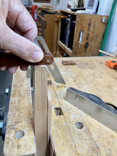
The armrests are attached with wedged, through mortise and tenon joints. The method that Mike Pekovich from Fine Woodworking Magazine uses is what I prefer too. Here’s a LINK to it but you may need to be a Fine Woodworking member. He utilizes a spacer to get the width just right, this way you only need to set your marking gauge one time. Only variation I did was to use a 3/8β€³ drill on the drill press to remove the bulk of the material. He uses a smaller bit and makes more holes; either way works. I could do this because my tenon is 7/16β€³ wide. I also used this method on the Japanese toolboxes for laying out both the mortise and the tenon. I’ve been presenting my work in a slide show format to simplify the blog β€” let me know if I succeeded!

  • Lay out on tape using spacer
  • Drill press to remove bulk
  • Chisel work to scribed lines
  • 2Β° angle for outer walls
  • 4Β° wedges
  • Kerfs and relief holes
  • Assembled armrest to legs

At this point this project is almost ready for final assembly. The last thing that needs to be done is to apply the Osmo to the leg and armrest assemblies. We get our foam at Galaxy Foam and Upholstery Supply here in Las Vegas. They have foams of all densities and wrap batting around it which makes for a better cushion. Also bought the material there and unfortunately it’s too thick for Diane’s machine so they are currently being sewn at Oscars Upholstery. I’ll do a final blog on this when the cushions are done and the love seat is ready. I’ve been told my blogs can get long winded but appreciate any comments or questions you may have, thanks β€” John

  •  

Crazy Challenge: Hexagon Box with Hinged Lid!

16 May 2025 at 18:44

Beginnings β€” it started out easy enough but that soon changed! I decided to see if I could construct a hexagon box that had a hinged lid. Why, just because I’d never done it or see it done! I wanted a better place to keep my Lie-Nielsen spokeshave than the cardboard box it came in. Since I had some Poplar in my shop decided to use that. Started by cutting 6 pieces at 30Β° and assembled them using packing tape, even book matched them– easy ’nuff!!

Now that I had a hexagon cylinder it needed the end pieces. Used a scrap of MDF to play with the sizing to match the outside of the hexagon. Once the miter saw was set with a stop block and the MDF fit well I cut the Poplar. The blade angel is 30Β°.

First cuts
Second cuts

I’m a tails first dovetailer and this took a bit of thinking and planning ahead. The first step was scribing the thickness of the box on both sides of the end pieces. The tails are at the and marked off with a pencil. Removal of the waste began by first deepening the scribed marks with a chisel. After cutting closely to the line those deeper lines made it easier to chop the shoulders square. Transferring to the hexagon began by scribing the thickness of the end pieces all around, both inside and outside of the hexagon. Then the end piece was positioned and the tails were transferred to the hexagon. Not much room to move a dovetail saw but that was the easier part. The waste can only be removed from the outside of the hexagon so I got creative in how to hold the hexagon. At this point, I think a slideshow will illustrate better than anything I write!

  • Tails laid out, scribing shoulders
  • Making scribe lines deeper made final chisel work easier
  • Fitting and scribing onto hexagon
  • Awkward position but able to chisel waste out
  • Used body weight to hold hexagon on scrap and chiseled out waste
  • Almost ready to glue

Once the box was glued up, I separated the lid on the bandsaw, I correctly assumed that cutting it would change the size so the lid was a bit smaller than the box. Another unforeseen problem is the the screws for the hinges were too long since they sit on a 30Β° angel β€” cut them shorter so there’s not a lot of purchase with them. I had a small piece of curly Spanish Cedar so used that for a lid lift and also the French fit insert to hold the spokeshave. Sorry, didn’t take any pictures of that process but it’s secured inside of the hexagon with silicone seal. The hinges and the lid lift are mortised in, quite different cutting a mortise on an angled piece of wood!

  • Cutting off the lid lift
  • Stanley #271 scribes depth of mortise
  • Mortise laid out
  • Progress on mortise
  • Mortise done!

All things considered, this was an interesting challenge and glad I took it on. I enjoy these types of projects, let me know if you too decide to try making one of these. Here’s a short video I posted to YouTube of the finished project, enjoy β€” John.

  •  

Book Excerpt: Tools by Theodore Gray

4 June 2024 at 15:37
Tools: A Visual Exploration of Implements & Devices in the Workshop If there’s one thing to be said about woodworkers, it’s that we’re old school and prefer to pick up a book (or a magazine). With that in mind, I’m …

Source

  •  

Z-Chair Project Completed!

19 November 2023 at 02:58
From patterns and wood to a completed chair!

I began working on this project in mid-September after doing research on the internet to find dimensions, other peoples projects, and images of the iconic Z-Chair. After creating patterns from MDF the first prototype was made from 6/4 Poplar. The majority of the information I found used either dowel construction or Festool Domino system. I’ve never been a fan of dowel construction as they can shrink and cause joint failure and since the Domino system, as great a tool as it is, starts at around $1100.00 it’s just too rich for my budget. I prefer the more traditional mortise and tenon joinery so that’s what I went with. Essentially the chair consists of a long member that forms the rear leg and angles to the front to support the arm rest. The front leg and back rest are attached with an angled tenon that is fitted into a mortise that was cut before the main, long member is shaped. This mortise started at 90Β° but after cutting the angle for the back rest and front leg the tenon needs to be approximately 15Β°. For more about that detail see my first blog on the project.

At the end of the last blog the sides of the chair and the seat frame were assembled and all of the pieces for the back were formed and the joinery was complete. The major part left was sculpting the arm rest. I changed the design and eliminated the scoop out that was a feature of the original chair. The arm rest remains flat on the bottom but the top is tapered from about 1 1/8β€³ at the back to 3/4β€³ at the front. I also created an upswept curve so when viewed from the side, the arm rest not only tapers from back to front but also on its edge. The pictures below show the process, after drawing in the limits of the curve a block plane was used to create a wide chamfer on the straight sections and the Stanley spokeshave for the curved areas. The curves were finalized with the Lie-Nielsen spokeshave. At first I was planning on chamfers for the front of the arm rest but that area felt better with a rounded over edge.

Penciled in lines to define shape
Creating chamfer prior to spokeshave work
Checking to make both arm rest ends similar β€” decided on round over

The way I decided to attach the arm rest is different from anything I saw in my research. It seems to me that this is the piece that holds the Z-shape together. Where it attaches to the backrest my choice was to use a draw bore mortise and tenon joint and where it attached to the main member there is a #0 biscuit. My thoughts are that the biscuit helped to align those pieces at the front and also strengthened it. Adding a 3/16β€³ peg (made from the Beech) stabilizes that area as well. It gave me the chance to use a tool I made when I built John’s Armoire and those joints are as tight as ever.

Tool used to locate center of draw bore, drilled slightly off center to pull tight into mortise
#0 biscuit at front of arm rest

The finish is Osmo PolyX #3043; a total of 3 coats were hand rubbed into the chair about 24 hours apart. The first two coats were applied with a gray nylon scrubby and the final coat with the finer, white scrubby β€” feels like glass! The final step was installing the webbing, I used metal clips that were attached to the webbing with a vise. My wife sewed up the upholstery with material from Wayfair. There is a place here in Las Vegas called Galaxy Foam, they supplied the 5β€³ thick foam for seat and 4β€³ for the back. I purchased the webbing and clips from HousetoHome on Etsy, this material worked great and had instructions which I needed! I made a short video showing the chair complete with the webbing, here’s a link to that: https://www.youtube.com/shorts/28XQsFYpQiE

All in all, this was a great and challenging project. The chair fits well with our homes decor and is a comfortable and stylish addition. Here’s one more picture of it, we’ll probably experiment with placing it in different locations to see where we feel it looks the best. If you’re planning to make your own version of this iconic chair feel free to reach out if you have questions.

  •  
❌